Crustal Architecture
Hastings Block
Our view of the architecture of the Hastings Block is discussed in some detail in Appendix A, building on earlier work of Lennox and Roberts (1988), Roberts et al. (1995) and Lennox et al. (1999). In summary (Fig. 5), Devonian-Carboniferous strata in this block are mainly flanked by Permian strata. Locally, there is a contact to the west between volcanic rocks (and associated ultramafic rocks of the Yarrol ophiolite, eg. Aitchison et al. 1994) and subduction complex strata. In the east, a narrow zone of faulted Permian strata separates the block from subduction complex rocks of the Port Macquarie block. Triassic strata obscure the southeastern part (Fig. 5).
A key feature is the doubly plunging Parrabel anticline that occupies the northern part of the block (Lennox and Roberts 1988). This D2 fold deforms older (S1) cleavage and folds and is locally overprinted by D3 folds (Lennox and Roberts 1988). In the northern broad hinge, dips in Late Carboniferous strata range from 50 to 35° and in early Permian sequences from 60 to 28° (unpublished data, Roberts et al. ). Early Permian shallow-water strata in the hinge of the Parrabel anticline pass north-eastwards (across faults) into undifferentiated deeper water strata that comprise the multiply deformed and metamorphosed fill of the early Permian Nambucca rift basin (Lennox et al. 1999). The western part of the Hastings Block consists of an east-younging Devonian-Carboniferous sequence that passes from the Devonian Bitter Ground Volcanics, and associated ultramafic units, up into the Carboniferous Mingaletta Formation (Fig. 5).
In Appendix 1 we present our reinterpretation of the Hastings Block that is based on figure 2 of Roberts et al. (1995). We suggest that the Parrabel anticline is a hangingwall anticline above an east-dipping thrust sytem; that an east-younging sequence lies in the footwall of this thrust stytem; and that the whole packet has been probably thrust west over rocks of the subduction complex (Figs. 11a, b).
This sequence lies in the footwall of a major east-dipping major thrust represented by the Bagnoo Fault and its inferred extensions to the north. This thrust and the folded D1 thrust above flank a relict steeply north-plunging syncline that may be complementary to the Parrabel Anticline (Fig. 10a,b and Appendix A.).
Figure 5. Geology of the Hastings Block
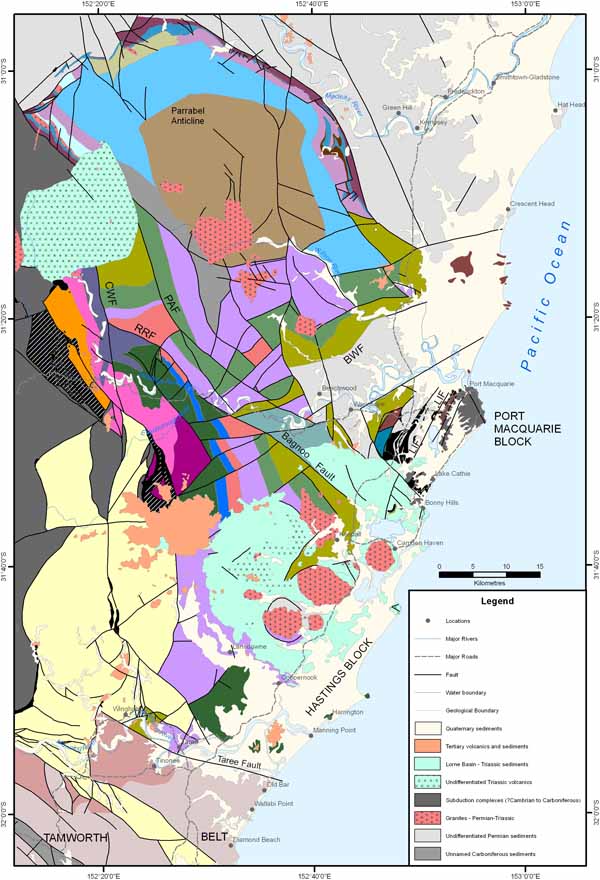
A. Geology of the Hastings Block, after figure 2 of Roberts et al. (1995). Abbreviations: BWF=Beechwood fault; CWF=Cowarral fault; LIF=Lake Innes fault; PAF=Pappinbarra fault; RRF=Rollans Road fault. B. Legend.
Northern Tamworth belt
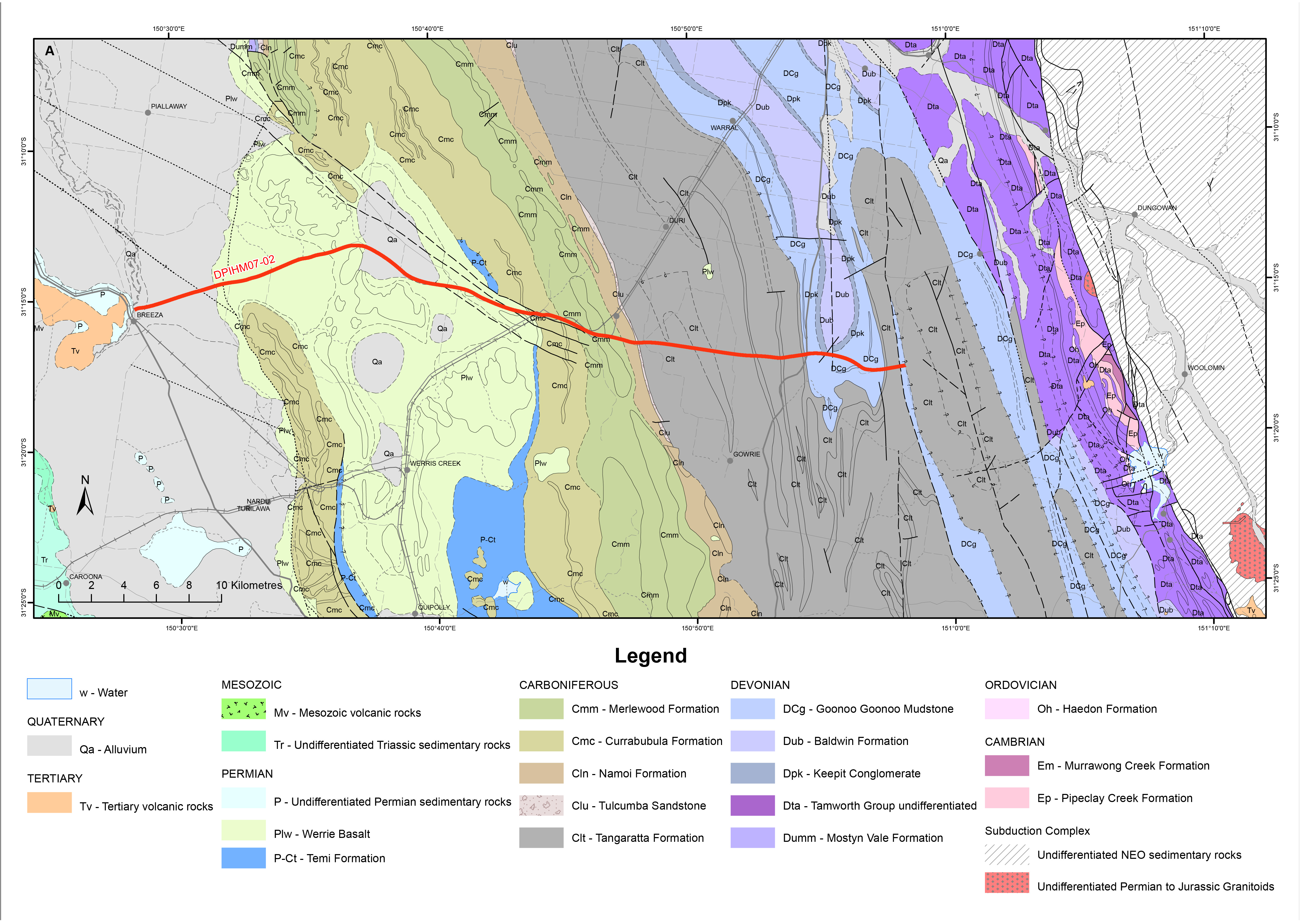
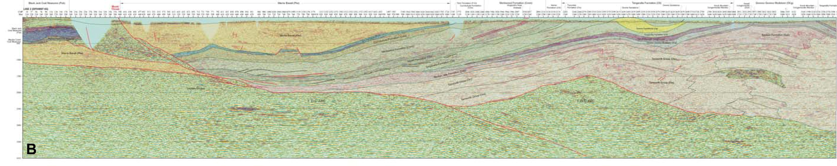
The northern part of the Tamworth belt has a relatively simple geometry east of the leading, N to NNW-trending, 170 km long Mooki Thrust (Fig. 3). Traces of major thrusts and folds lie parallel to the eastern boundary of the forearc basin (except for possible local duplex formation, Woodward 1995), and are thus inferred to lie subparallel to the old continental margin. They reflect shortening at high angles to this margin.
An example of the structure of this region is shown in Fig. 6a in map view and 6b in section view. In section, the upper crustal architecture is controlled by an east-dipping detachment fault that has transported the forearc basin, over inferred basement of accreted Silurian–Devonian arc in the east and over a footwall in the west that is inferred to represent the missing and underthrust Devonian-Carboniferous arc. The detachment rises from a depth of ~3.5 seconds two-way travel time (~12 km) to become subhorizontal or shallowly dipping under the the lower coal measures or the underlying early Permian volcanics of the Gunnedah Basin (Fig. 6b). A stair-tread geometry produces regional folds in the hangingwall. The frontal Mooki Thrust splays off the detachment where it truncates the leading limb of frontal hangingwall syncline that is cored by Permian strata. An additional deeper detachment is inferred at the base of the accreted Silurian–Devonian arc of the Tamworth Group.
Figure 6. Representative part of the northern Tamworth belt
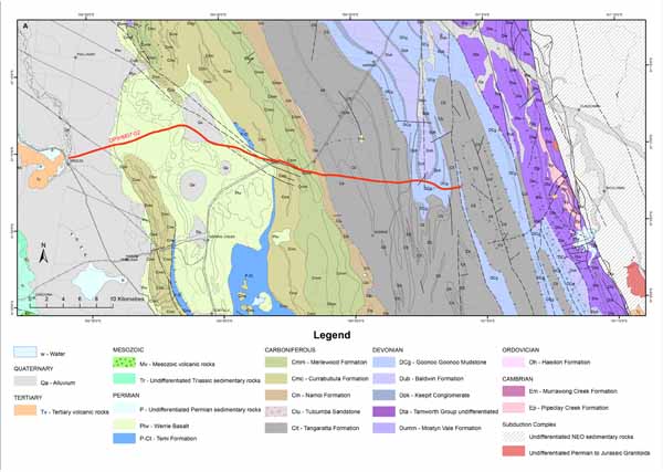
Representative part of the northern Tamworth belt showing A. simplified geology, and B preliminary interpretation of seismic section DPIHM07-02. Vertical scale is in seconds of two way travel time, with 1 sec approx = 3 km. Ratio is approximately 1:1.
Southern Tamworth belt
Structures in the southern Tamworth belt are much more complex, reflecting multiple deformation in which structures parallel to the continental margin have been overprinted by younger structures that lie at high angles to the plate boundary.
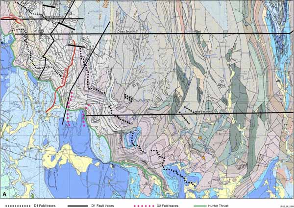
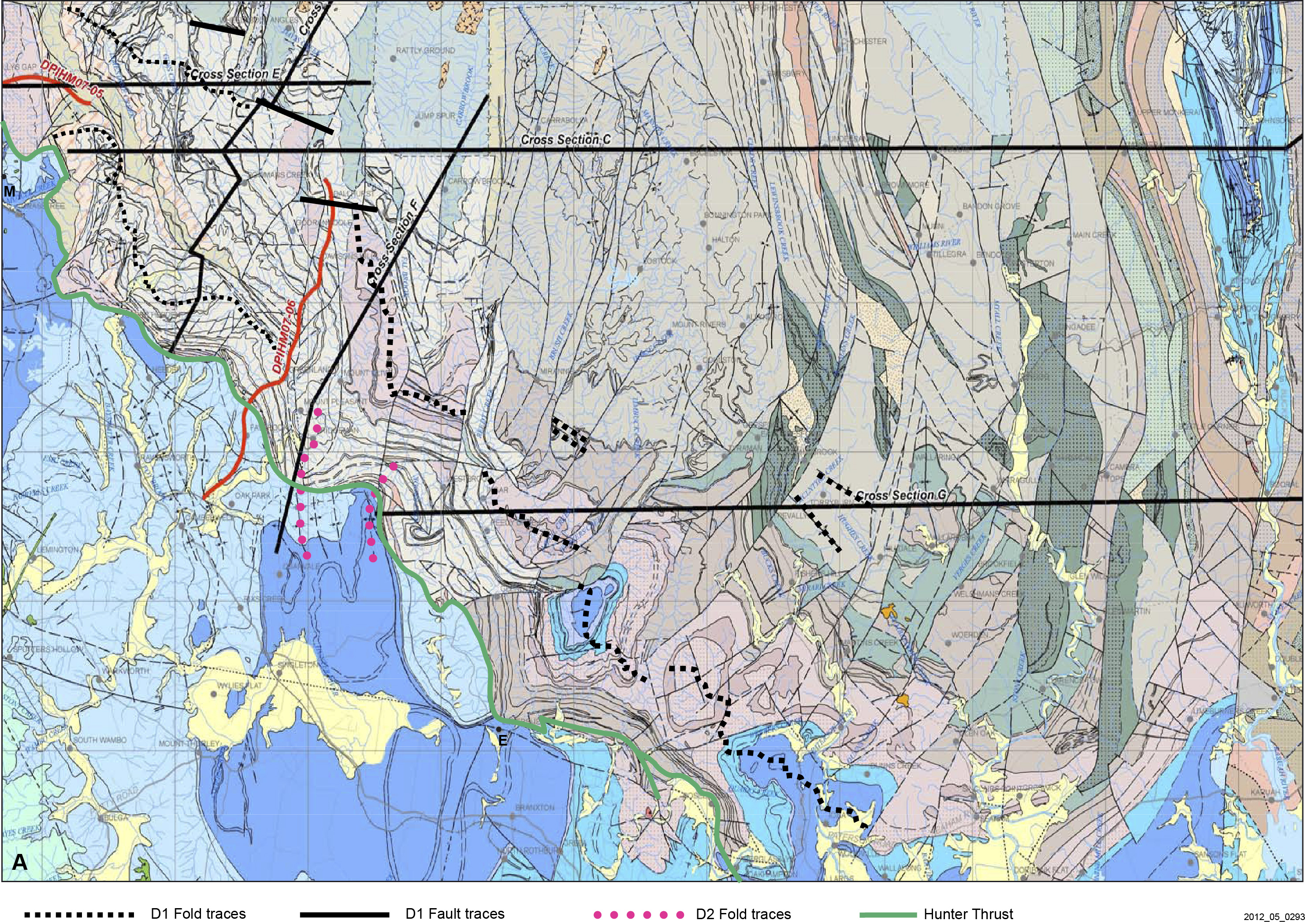
The Hunter Thrust separates the Tamworth belt from the Sydney Basin. It trends south for 65 km from the Murrurundi Fault to Muswellbrook (Fig. 3), comprising individual segments cut by latitudinal cross structures (Glen and Roberts work in progress). South of Muswellbrook, the Hunter Thrust swings to the SE and ESE for ~70 km, and is not only folded (Glen and Beckett 1997) (Fig. 7a), but loses stratigraphic separation to the southeast before dying out in the Bolwarra Anticline, 3 km NNE of Maitland and 35 km WNW of Newcastle (Glen 1993) (Fig. 7b). As a result, Permian strata of the Dalwood Group to the northeast lie unconformably above forearc basin rocks (Fig. 7b). The greater complexity of deformation in this southern region reflects the overprinting of early orogen–parallel D1 structures by D2 folds and faults that have N and NE-trends in the west and N-to NNW trends farther east (Fig. 7a). D2 intensity increases from west to east. From the town of Muswellbrook eastwards to the town of Elderslie, D1 folds and thrusts can be can be easily recognised at map scale, despite being overprinted by D2 structures (Figs. 4, 7a). However, from Elderslie eastwards, mapscale D1 continuity is not so obvious. While present in between D2 faults close to the southern margin of the New England Orogen, continuity is lost in the northern part where more intense strain has produced panels of stratigraphy swinging from NNE to NNW (Figs. 4, 7a). Greater D2 strain occurs from the Stroud-Gloucester syncline eastwards to the coast where all the forearc basin units lie parallel to D2 thrust slices that fan in strike from N to NNW (Fig. 4). Since these D2 structures reflect approximately east-west contraction, cross sections drawn NE-SW lie parallel to D1 transport directions, whereas E-W sections reflect the D2 geometry and transport.
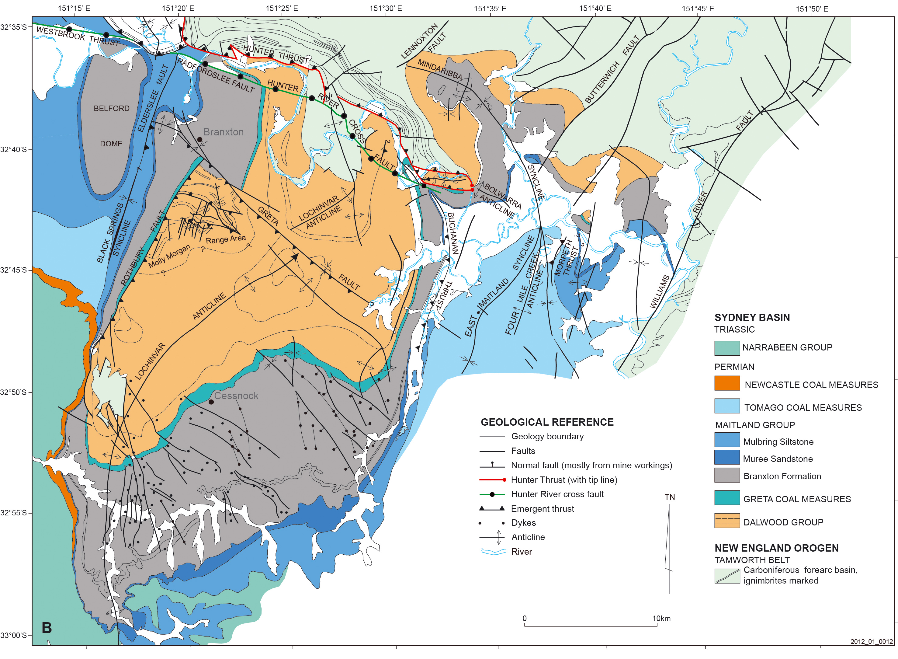
Figure 7. Southern Tamworth belt

A. Simplified map of southern part of the Tamworth belt showing folded Hunter Thrust, separating blue Permian units to the south and coloured Carboniferous units to the north, and D1 structures folded by D2 structures. Blue-coloured units on easterm margin are the Stroud-Gloucester Syncline in the north and the Medowie faulted syncline in the south. Map faces north, with grid squares 10 km across. B. map showing southern termination of Hunter Thrust, and resultant conformable contacts between Carboniferous and Permian strata to the northeast (from Glen 1993).
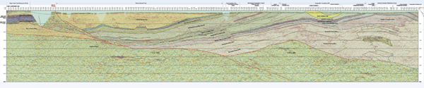
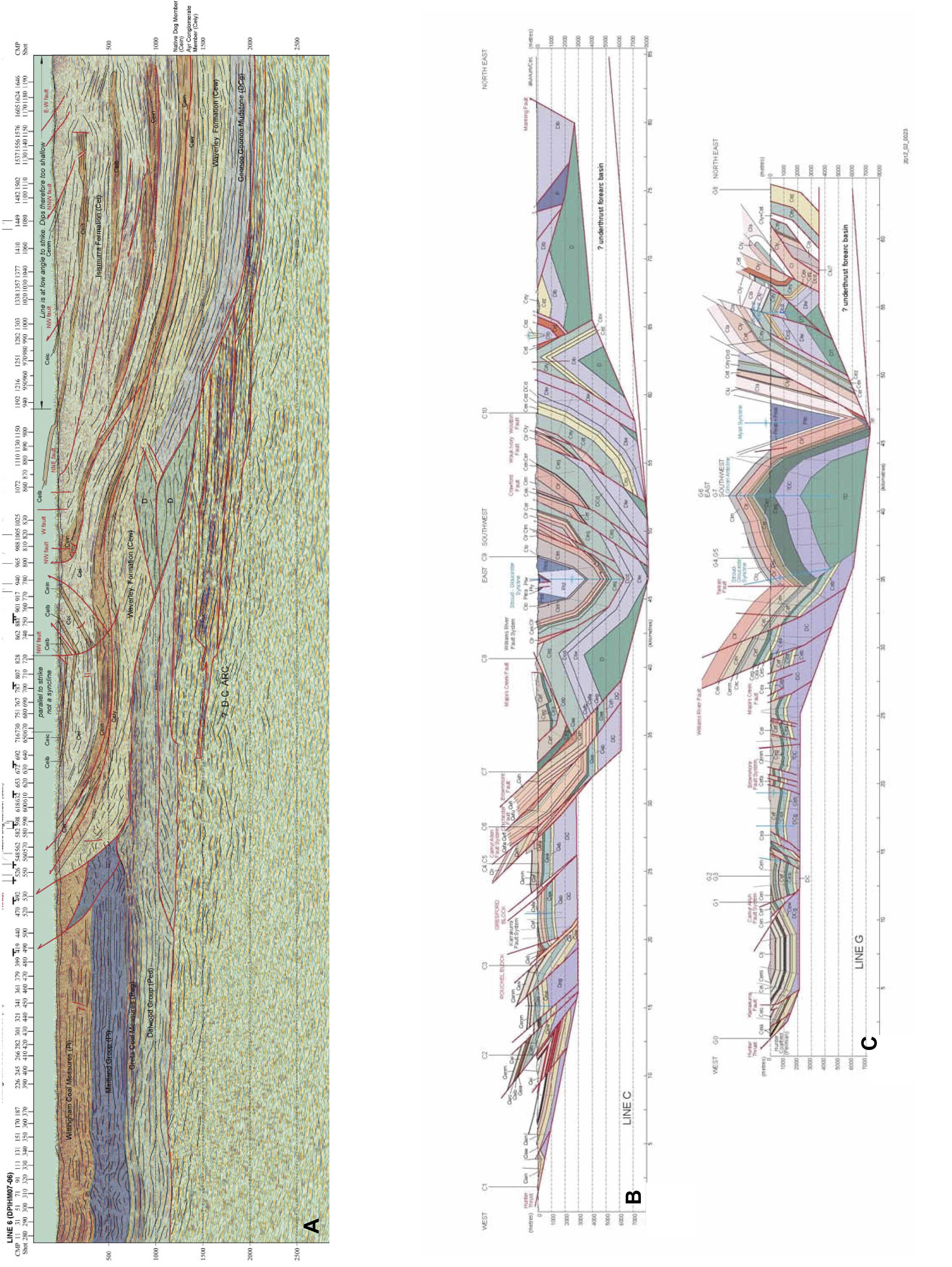
Seismic section DPIHM07-06 (Fig. 7a) lies perpendicular to the Hunter Thrust and extends from the Sydney basin in the southwest into the forearc basin. The geometry of Fig. 8a shows that the upper 1 sec twt (~3 km) of the eastern part of the line is distorted by lying subparallel to regional strike. The lower part shows a regional NE-dipping detachment, with stair-tread geometry, that has transported the forearc basin over inferred reflective Devonian-Carboniferous arc volcanic rocks in the footwall.
Sections C and G (located in Fig. 7a) run west-east, approximately normal to D2 structures (Figs. 8b, c). In summary, they show a tripartite subdivision: a western, west-verging part, in which forearc strata, cut mainly by west-dipping thrusts, lie above a regional detachment; a central zone marked by a western anticline and eastern syncline, the latter cored by Permian strata, and shown as extending in depth to 7-8 km; and an eastern zone marked by east-verging thrusts inferred to overlie a west-dipping detachment with stair-tread geometry.
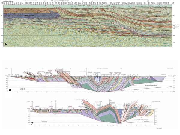
Figure 8. Cross sections through southern Tamworth belt
A. SW-NE preliminary cross section along seismic line DPHM07-06 and drawn perpendicular to D1 thrusts. B. Preliminary cross sections C and G drawn from west to east, perpendicular to D2 structures overprinting D1 thrusts in the southern part of the Tamworth belt. Geology of the Stroud-Gloucester Syncline has been simplified. For locations and key to letter symbols, see figures 4 and 7a.
Offshore Uplift
Diessel (1980) reported an easterly (offshore) source for late Permian sediments at Newcastle and Jones et al. (1984) suggested that this source was the offshore continuation of the New England Orogen (called the Currarong Orogen) which had wrapped around the Newcastle recess. Petroleum exploration has provided more information. Offshore from the Sydney basin there are three main structures: the Offshore Syncline in the west, the Offshore Uplift in the east, and to its north, the Newcastle Syncline (Grybowski 1992; Bradley 1993; Alder et al. 1998; Bounty 2002; Breeze 2009) (Fig.1 b). Aeromagnetic data (Fig. 9a) suggest that the core of the Offshore Uplift has similar properties to, and is continuous (across the Newcastle Syncline), with the Carboniferous continental margin arc volcanic rocks at Port Stephens and the inferred volcanic centre that lay just to the south (Buck 1998) (Fig. 1b). Above these rocks are inferred Permian to Cainozoic strata (Breeze 2009) (Fig. 9b). Seismic interpretations (Alder et al. 1998; Breeze 2009) suggest that the Offshore Uplift has been thrust NNE over Permian strata in the Newcastle Syncline (Fig. 9b) in Permian times, with a similar overthrust relationship along the margin between the Offshore Uplift and the Offshore Syncline (Fig. 9c).
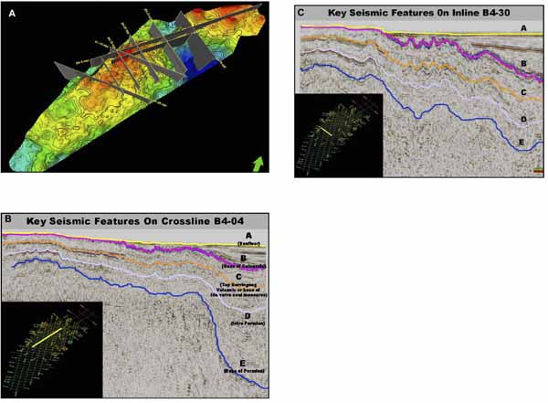
Figure 9. The Offhore Uplift
A. Aeromagnetic map of Offshore Uplift (see Fig. 1b for location and shape) passing NNE into Newcastle Syncline (blue colours) and then into volcanic centre south and at Port Stephens (Bounty Oil and Gas 2002). B and C interpreted seismic sections showing picks of key stratigraphic horizons, from Breeze (2009) with permission. B. Section oriented SW-NE from left to right, from Offshore Uplift into Newcastle Syncline. C. Section oriented WNW from left to right from Offhore Uplift into Offshore Syncline. Structural elevation in both sections is inferred to reflect the presence of dipping thrusts