Microstructural analysis
Samples and reference system
In this section the main objective is to characterize the evolution of microstructure across an ideal strain gradient, through the Bazar shear zone. From lower to higher strain we find: a) relics of metagabbros and HT-amphibolites, at different scales and degree of retrogression. They are considered the mylonite protholiths. b) Mylonites, which range from protomylonites to ultramylonites. Protomylonites correspond to amphibolites with a significant volume of protholith features, particularly, brown amphibole (am1). Ultramylonites depict no relics of the protholith.
Observations were carried out with petrographic microscopes on polished rock and thin sections cut perpendicular to the foliation (Sm) and parallel to the lineation (Lm) (XZ plane; Fig. 4). Mylonitic foliation at the outcrop scale correlates with microscopic layering (Sm), defined by alternation of amphibole- and plagioclase- rich mylonitic domains.
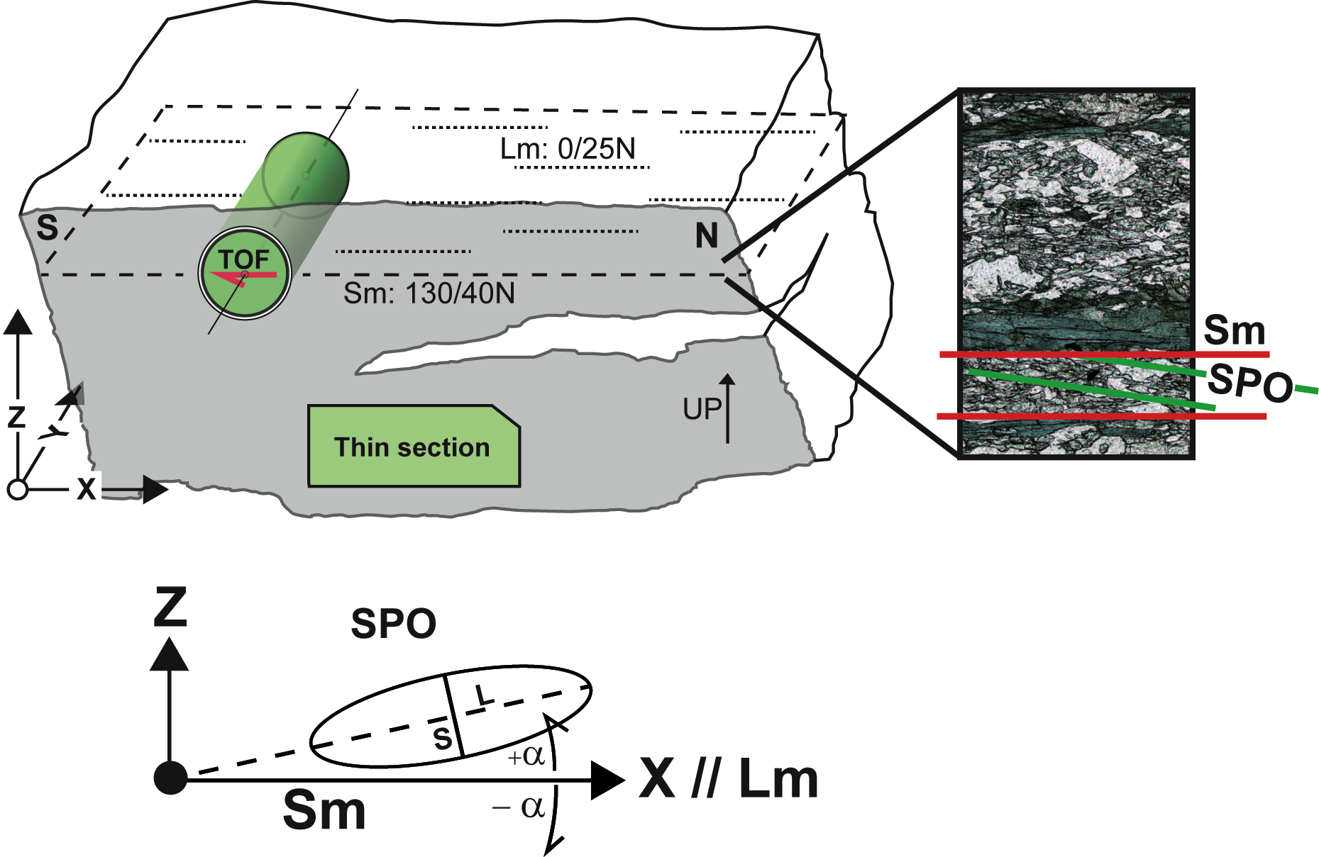
Figure 4. Reference system for microstructural and texture analyses

XYZ reference system for microstructural and texture analyses, where X is parallel to the mineral lineation (Lm), and XY to the foliation (Sm). A cylinder parallel to Y and perpendicular to X with a red arrow on top was drilled for TOF texture analysis. A detailed inset shows the fabric elements of an ultramylonitic level. Sm is defined by the compositional layers, being parallel to the shear zone boundary. A shape preferred orientation (SPO) fabric is identified inside each layer, with a monoclinic symmetry, showing a top-to-the S sense of shear. In the lower part, the reference system for SPO analysis is depicted: shape ratio (SR = Long/Short) and orientation (α = (º)) is defined by fitting an ellipse to each grain. See the main text for a disscusion.
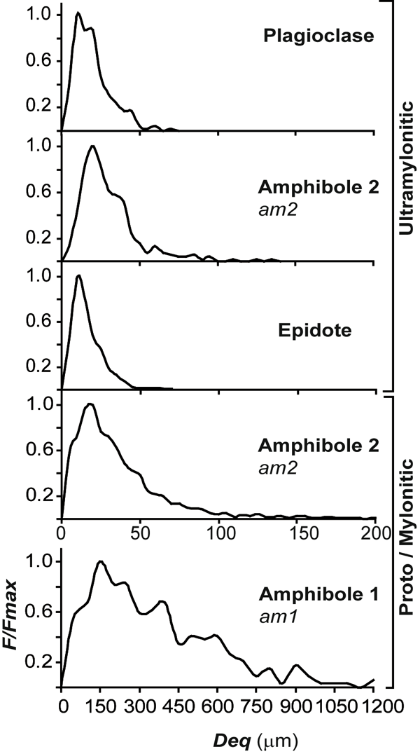
Manually digitized micrographs were analyzed with ImageJ, version 1.4 (W. S. Rasband, U.S. National Institute of Health, http://rsb.info.nih.gov/ij/, 1997–2011), and SPO 2003, version 6, software (Launeau and Robin 1996; http://www.sciences.univ-nantes.fr/geol/UMR6112/SPO).The grain size (Deq) is defined as the diameter of the equivalent circle with the same area (A) as the measured grain (Deq2 = 4A/π; Heilbronner and Bruhn 1998). Selected grain size distributions are plotted using a normalized frequency (F/ Fmax, Fig. 5), but in general, results are presented in parametric form (Table 1).


The shape ratio (SR) and the long-axis orientation of each grain (α) are calculated from the inertia tensor of its shape, (Jähne 1991) (Fig. 4). The SR/α graphs were constructed from those data (Fig. 6). Bulk SPOs (SRt, Φ), were calculated by averaging the inertia tensor of each grain, resulting in an SPO weighted by the area of each grain (Launeau and Cruden 1998). Bulk SPOs were used to correlate different aggregates across the shear zone, and the relative contribution of each rock type to the general fabric (Fig. 7) (Gómez Barreiro et al., 2010a). Microcracks are observed in amphibole porphyroclasts (am1) of mylonites, and included in the discussion about deformation mechanisms (Nyman et al. 1992; Shelley 1994; Imon et al. 2004). Main results of the analysis are presented in Table 1.
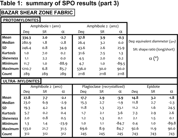
Figure 5. Grain size distribution of main phases
Grain size distribution of main phases in protomylonites/ mylonites and ultramylonites. Normalized frequency (F/Fmax) of the grain equivalent diameter (Deq) is plotted.
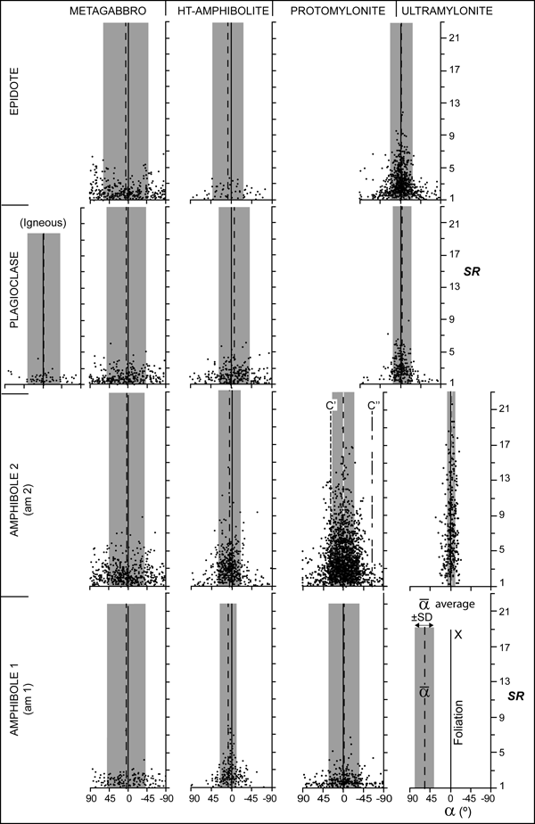
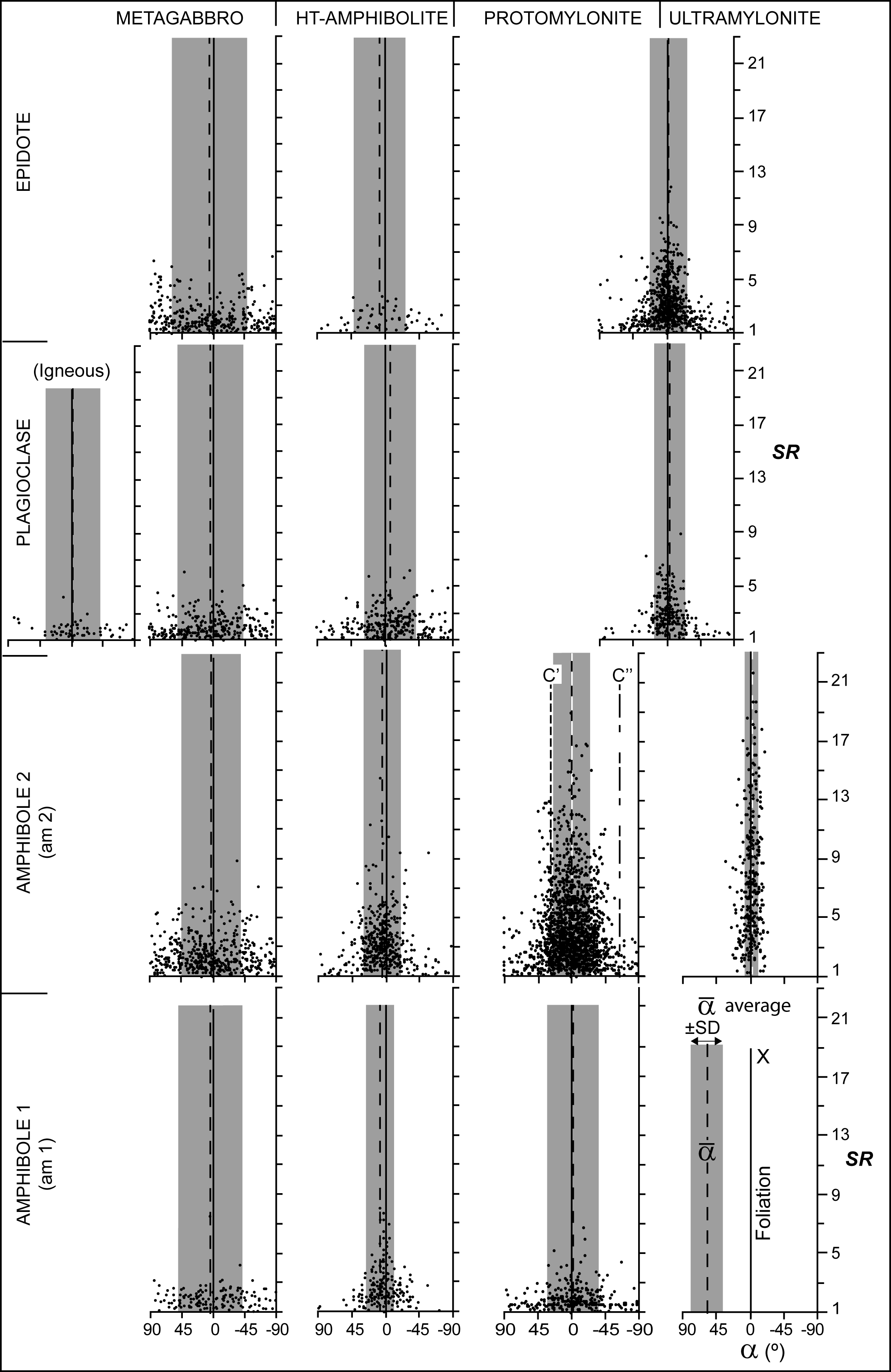
Figure 6. SR/α graphs for main mineral phases and rock types
SR/α graphs for main mineral phases and rock types. In all cases minerals become more elongated as deformation increase. The dispersion of the grain orientation (SD) is reduced within mylonites, except by amphibole 1 (am1). This is probably explained by the rigid behavior of the am1 grains (porphyroclasts) and the abundance of C’C’’ shear bands which deflect the mylonitic foliation. Solid line represents foliation (XY plane; Fig. 4), dashed line, the average grain orientation (α), and the grey bar, the standard deviation (±SD) of α (Table 1). The orientation of shear bands C’ and C’’ are plotted for protomylonites. See the text for a disscusion.
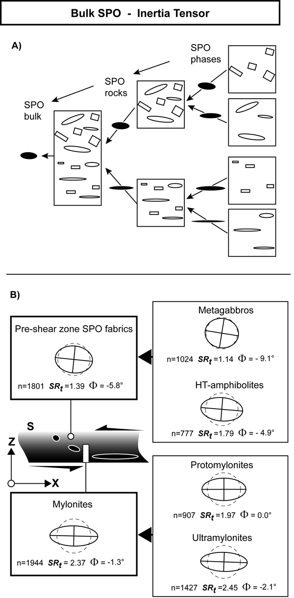
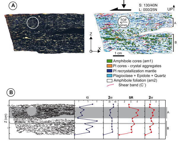
Figure 7. Bulk shape preferred orientation
Bulk shape preferred orientation, SPO, (SRt, Φ), were calculated in different steps by averaging the inertia tensor of each grain, weighted by each area (Launeau and Cruden, 1998). (A) All mineral phases are included, resulting in a mean inertia tensor for each lithology. Digitized grain boundaries were scaled and same area for each rock type combined to build a representation of mylonitic and pre-mylonitic fabric. (B) Metagabbroic rocks show a very weak SPO, while HT-amphibolites define a weak to moderate fabric. Combining both microstructures a bulk SPO for pre-shear zone fabric is obtained. As explained in the text, some synkinematic phases exist both in metagabbros and HT-amphibolites, so bulk SPO should be interpreted as very low strain rocks within the shear zone (small inset). Mylonites are made of proto to ultramylonites. The combination of those domains results in a strong bulk SPO.
Mylonite protholiths: Metagabbros and HT-amphibolites
The preservation of an igneous texture in metagabbros is distinct and results in a very rough (if any) foliation (Figs 6 and 7B). New phases grew and mimic the old igneous texture, which lead to a bulk random shape fabric (SRt =1.14, Φ= -9.1º). In HT-amphibolites, a foliation is defined (SRt =1.79, Φ= -4.9º) by the preferred orientation of amphiboles (am1), and some lensoid domains of recrystallized plagioclase. As a whole, mylonite protholiths depict a low bulk SPO (SRt =1.39 ; Φ= -5.8º; Fig. 7B) with a monoclinic symmetry that suggests a top-to-the S sense of shear.. The contribution of the principal mineral phases is explored below (Fig. 6).
Plagioclase: igneous plagioclases have been completely replaced by polycrystalline aggregates of metamorphic plagioclase and epidote (Fig. 3). Igneous grain shapes are still recognizable, and show mean grain size and shape ratio of Deq = 402.5 μm and SR = 1.9, respectively. Recrystallized plagioclase results in a drastic grain size reduction, with a mean grain size Deq = 51.6 - 79.6 μm, for metagabbros and HT- amphibolites. Shape ratio shows no significant variation SR = 2.0 - 2.2 (Table 1). All plagioclase grains show a poor preferred orientarion (α ~ 3º ± 45; Fig. 6; Table 1). Grains with undulose extinction are common and subgrains are found in larger grains.
Amphibole: Brownish amphibole with inclusions (am1) shows a similar grain size than igneous plagioclase, in both rock types (Deq = 421.4 - 426.6 μm). However, those grains in HT-amphibolites are more elongated (SRHT-amp = 2.6 vs SRMetagabbro = 2.0), and oriented (α HT-amp ~ 6º ± 19 vs α Metagabbro ~ 4º ± 45; Fig. 6; Table 1). Interestingly blue amphiboles (am2) in both rocks present a similar relationship. Scarce undulose extinction and twins are found in both types of amphiboles.
Epidote: epidote crystals have a similar behaviour in metagabbros and HT-amphibolites. Grain size is moderately higher in the second lithology (Deq Metagabbro = 73 μm vs Deq HT-amp = 103 μm; Table 1). Shape ratio shows no significant variation, SR = 2.0 - 2.3. Grain orientation presents a similar trend than amphiboles.
Mylonites
In deformed metabasites the mineral assemblage of microstructural domains are similar, but variation of modal proportion are important, correlating with the progressive deformation of metabasites into the shear zone. Protomylonitic domains appear surrounded by mylonitic and ultramylonitic ones at different scales (Fig. 3).
Shear bands and microdomains
Microdomains in mylonites were analyzed first in polished rock section (XZ) (Fig. 8A). Scanned images where processed into ImageJ in order to perform image segmentation based on gray-levels and colour histograms (e.g. Zucali, 2011). Dark rounded porphyroclasts of amphibole (am1), plagioclase porphyroclastic cores, recrystallized mantles, and mixtures of plagioclase, epidote and quartz, were identified within a mass of green amphibole (am2) (Fig. 8A). Shear bands show a coherent top-to-the S sense of shear, with the development of two different sets: C’ and C’’ (Fig. 8 and 9). The presence of SC’C’’ has been interpreted as developed in stretching shear zones (Passchier, 1991), which means that the shortening direction lies at a relatively high angle to the shear plane, resulting in an effective extension along the flow direction (Passchier and Trouw, 1996).
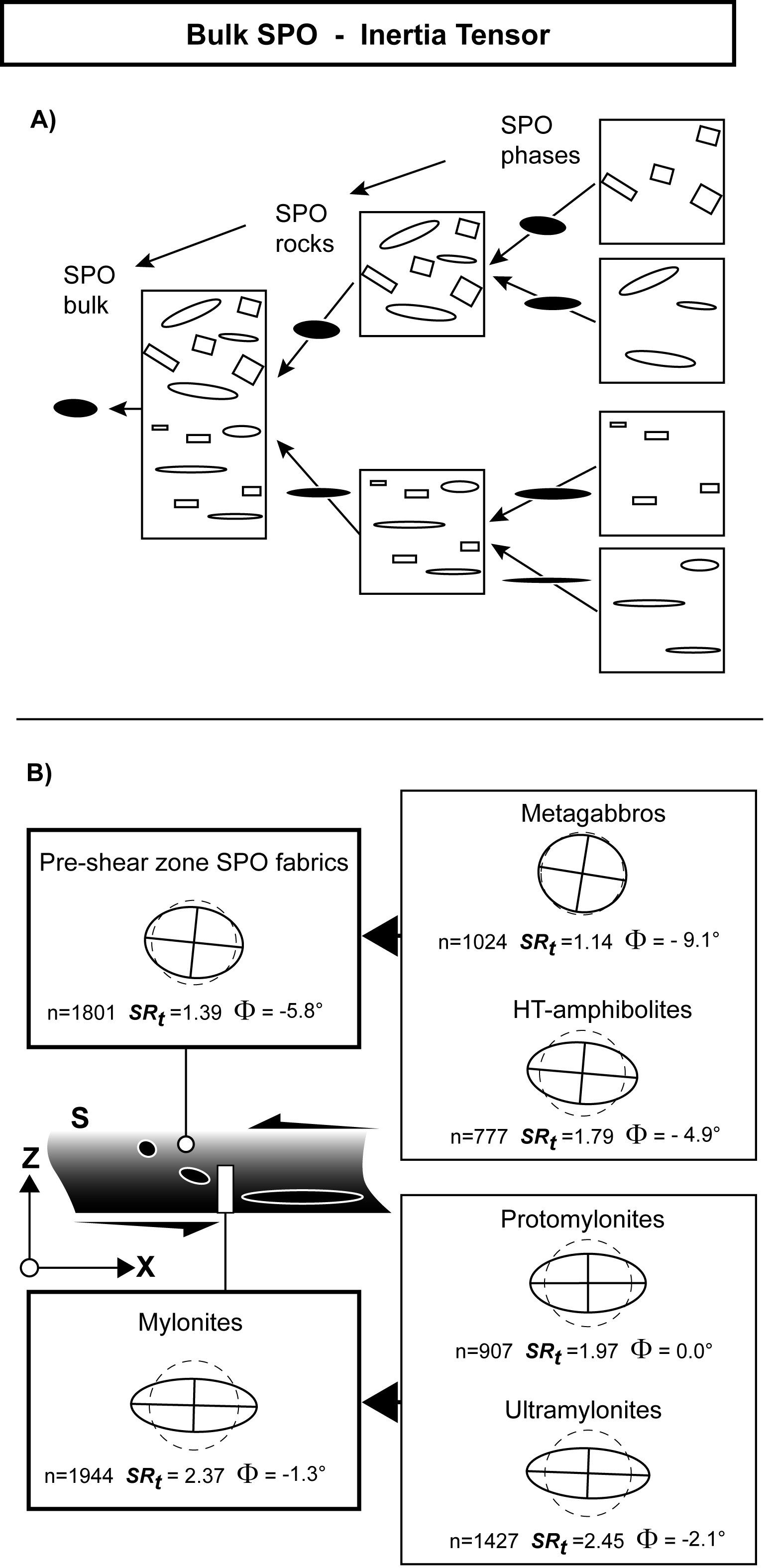
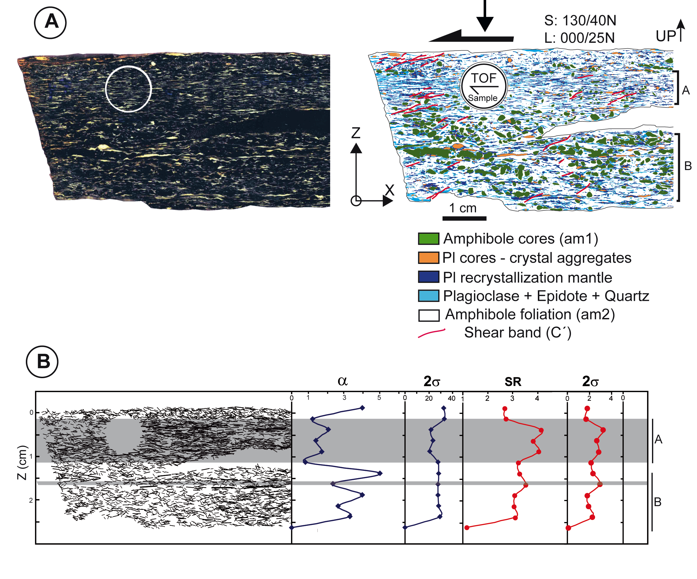
Figure 8. Fabric analysis on polished mylonite sections
Fabric analysis on polished rock sections. An example of common mylonite is presented in (A). Image analysis is used to discriminate different microstructural domains and major shear bands. Ultramylonitic (A) and protomylonitic (B) layers were analyzed by measuring the shape ratio and orientation (SR, α) of the weakest domains (blue ribbons). B) Spatial projection of the weakest domains results into a distribution of ultramylonitic and protomylonitic layers in the sample (stick bar length is proportional to SR). A correlation between orientation and shape ratio and the dispersion (standard deviation; 2σ), and microstructural domains arise. This analysis was the base for TOF analysis sample preparation.
Figure 9. Shear bands analysis
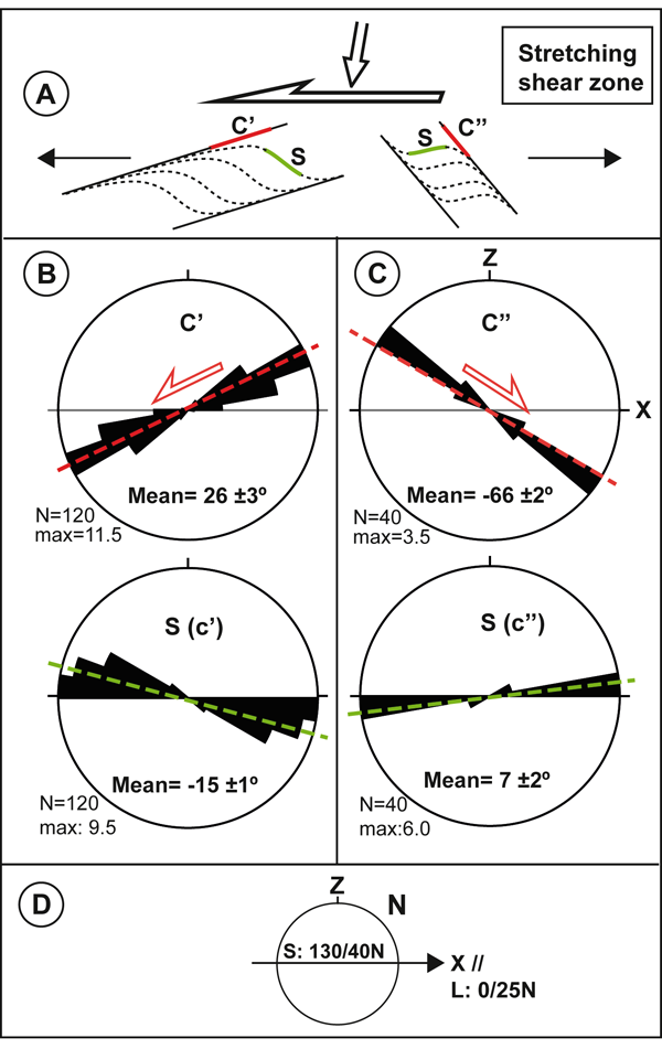
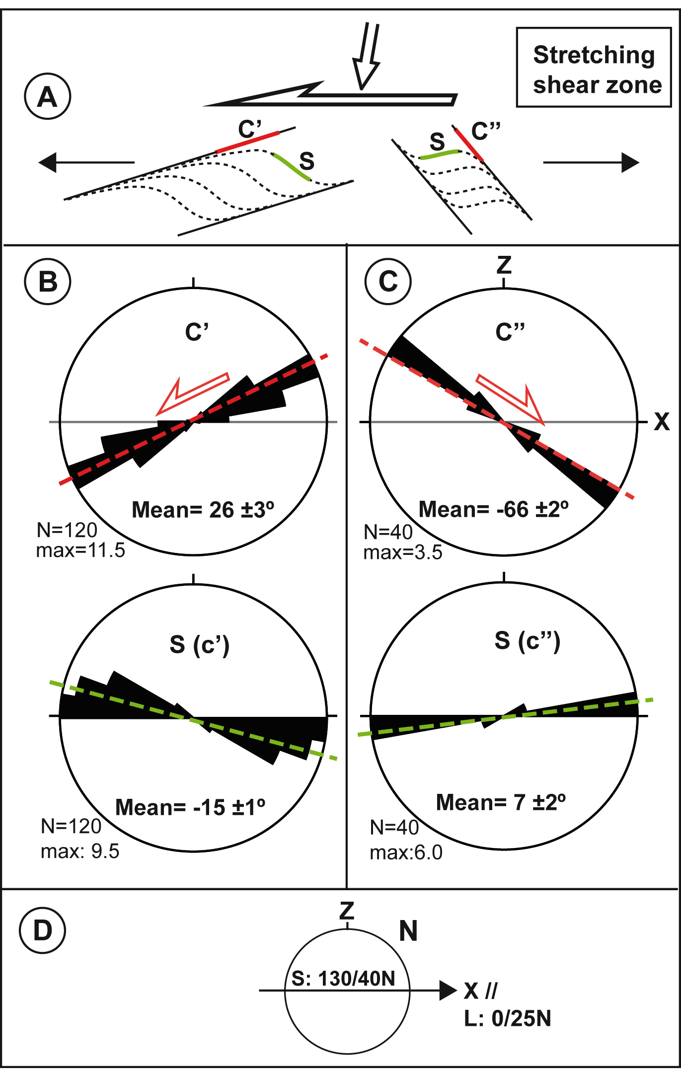
(A) Development model of SC’C’’ shear bands in a stretching shear zone (after Passchier and Trouw, 1996). (B) and (C) Rose diagrams of C’ and C’’ planes in mylonites and corresponding S planes. Results are coherent with a top-to-the S sense of shear. (D) Reference system.
Our results (Fig. 8) demonstrate that the deformation is heterogeneous and two distinct domains are formed at this scale: A) mylonitic/ultramylonitic (SR ~ 4 ; α ~ 1.5º ± 20) and B) protomylonitic (SR ~ 3 ; α ~ 4º ± 30) (Fig. 8A, B). In ultramylonitic domain (thick grey bands, A; Fig. 8B) highly elongated bands of plagioclase, epidote, and blue amphibole (am2) define a strong fabric, while in domain B, porphyroclasts of dark amphibole (am1) depict lensoid aggregates, commonly bounded by shear bands (SC’C’’). The development of synthetic (C’) and antithetic (C’’) shear bands is coherent with the sense of shearing (Fig. 9).
Mylonites
The bulk shape fabric (SRt ; Φ) of these domains increase from protomylonites to ultramylonites, (SRt ~ 1.97 – 2.45 ; Φ ~ 0º - -2.1º), and is stronger than bulk SPO in metagabbros and HT-amphibolites. On average SPO’s show a monoclinic symmetry for all phases, coherent with a top-to-the S sense of shear, but the angle to the shear plane (Φ, α), is lower than in metagabbros and HT-amphibolites. A typical mylonitic volume would depict a bulk SPO of SRt = 2.37 and Φ = -1.3 (Fig. 7). At the microscopic scale, a grain size reduction between 20 - 80% is confirmed in different phases with respect to the protholiths (Table 1; Fig. 5). Synkinematic phases (amphibole 2, plagioclase and epidote) show a stronger shape fabric as deformation increase (Table 1 and Fig. 6).
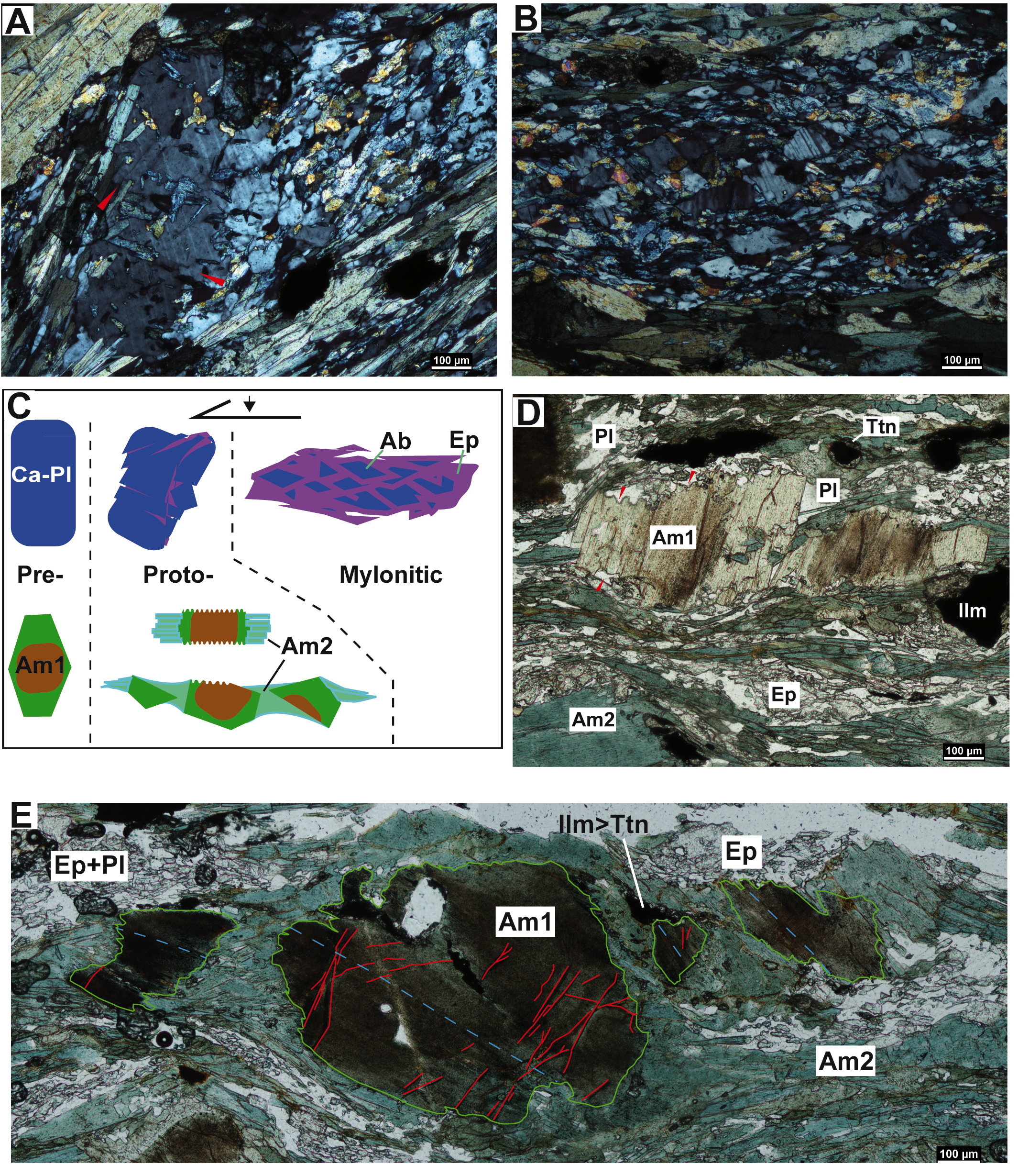
In protomylonitic domains, undulose extinction and rare subgrains are found in plagioclase grains. Besides, the shrinkage of plagioclase porphyroclasts (sensu Kenkmann, 2000) into the epidote – plagioclase matrix in mylonitic and ultramylonitic domains is illustrated in Fig. 10A, B, and C. Sligthly missoriented domains in a plagioclase prophyroclast in Fig 3A are limited by microcracks. Coeval growth of epidote crystals along those cracks and progressive rotations of fragments led to a complete shrinkage of the clast into the matrix in Fig 3B.
Brown amphibole (am1) porphyroclasts show a widespread development of intragrain microcracks (Fig. 3 and 10E). The tensional character of those cracks is recognized elsewhere, with amphibole am2 growing perpendicular to the crack-wall between the fragments. Moreover, textural zoning in am1 porphyroclasts are frequently truncated at those faces parallel to the foliation (Fig. 10D). In additon, a preferred growth of blue amphibole (am2) prisms occurs at faces perpendicular to the mylonitic foliation (Fig 3 and 10D-E). If we consider the geometry of the system am1 (core) – am2 (strain fringes), most grains show a monoclinic symmetry, supporting a top-to-the S shearing, or an orthorhombic symmetry coherent with a stretching component parallel to the mineral lineation (Fig. 3).
Figure 10. Microstructural evidence of solution-transfer creep and brittle mechanisms.

Microstructural evidence of solution transfer creep and brittle mechanisms. (A) Large plagioclase grains in ultramylonitic domains are transformed into a plagioclase + epidote (± quartz) matrix by a combination of microcracking (red arrows) and precipitation of other phases (e.g. epidote). (B) Eventually the initial plagioclase porphyroclast is converted in a polyclast of different grains with a relative missorientation, surrounded by a network of new phases (e.g. epidote, quartz, albite…). (C) Conceptual model of the processes illustrated in A, B, D, and E. (D) Evidence of dissolution-precipitation in amphibole. Truncation of the am1 grain zoning in faces parallel to the foliation. The truncation surface shows a stylolite-like geometry and could be interpreted as a dissolution front (red arrows). Plagioclase and blue amphibole (am2) crystallize in the am1 pressure shadows. (E) Microcracking and solution-precipitation mechanisms in amphibole. Main intragrain cracks are drawn in red. Dashed blue line mark the (hk0) trace.