Introduction
Focal mechanism solutions (also known as fault plane solutions) are critical to the evaluation of earthquake hazards and to understanding the spatial and temporal distribution of historic seismicity in relation to local volcanism and global tectonism (McNutt & Sánchez, 2000, Scholz 2002, Stein & Wysession 2002, Lisa, et al. 2004). Assuming a simple double-couple motion with no component of displacement normal to the fault plan, a focal mechanism consists of a representation of the orientation of the plane of failure combined with the direction of slip within that plane. Seismic first motion data analysis generally yields two nodal planes, the actual failure plane, and a second “auxiliary” plane oriented perpendicular to the slip vector. Additional factors, including tectonic setting and spatial distribution of seismicity must be considered in order to pick the fault plane and often the ambiguity remains unresolved. Traditionally, focal mechanism are viewed diagrammatically using so-called geophysical beach balls – projections of the focal sphere (Figure 1).
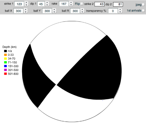
Figure 1. Focal Mechanism Diagram
Focal mechanism “beach ball” for an oblique slip fault. Lower hemisphere stereographic projection. Construction is fully discussed in De Paor et al. (2006). See also Glossary and Cronin (2005).
Geophysical beach balls are lower hemispheric stereographic projections centered on the earthquake hypocenter that show directions of contractional first motions (white) versus dilatational first motions (shaded) separated by two orthogonal great circles representing the two nodal planes. They are constructed based on records from global receiver stations that experience “up” versus “down” first ground motions. Commonly, the radius of the projection is scaled to the earthquake’s magnitude and sometimes the shading is colored corresponding to depth. Construction of focal mechanism beach balls is discussed in detail in Cronin (2005) and De Paor et al. (2006). We are concerned here with the task of representing focal mechanisms on Google Earth and other virtual globes.
Google Earth™ was chosen over alternative virtual globes such as MS Virtual Earth™, Arc Explorer™, Earth Browser™, etc. because it is customizable using Keyhole Markup Language (KML), a dialect of eXtensible Markup Language (XML). The author had been developing structural visualizations using XML-based Tectonic Markup Language (De Paor 1999, Babaie & Babaie 2002) and so conversion to KML was relatively straightforward. NASA World Wind opens KML files but does not yet have a full implementation of all KML version 2.1 features, including solid models. Future development of its open source code may enable the models presented here to be viewed in World Wind.