Tectonic reconstructions using deformable mesh software
Plate tectonic theory has evolved largely using the notion of rigid plates. Accordingly, the movement of plates (on the sphere) can be exactly described using rotations, typically specified by the Euler pole (axis) and rotation angle. However, the continental masses do not behave rigidly, and therefore this has been a mismatch in terms of geodynamic theory. It has been possible approximate the continuous deformation of orogenic belts by using rigid sub-plates, but such applications eventually require many different hierarchical movements. To allow plate tectonic theory to be extended to take account of the deformation of continents, and marginal orogens, a new generation of reconstruction software is necessary.
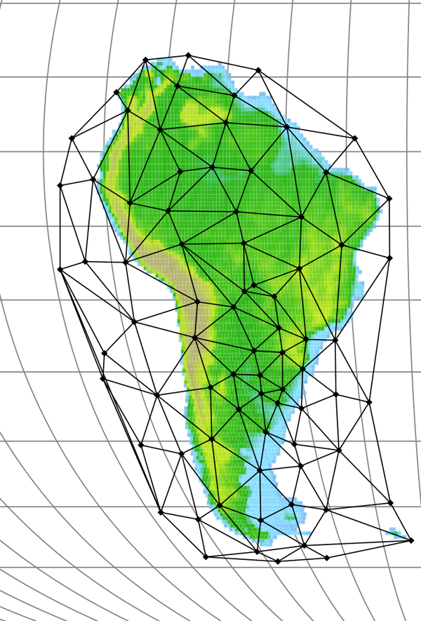
Pplates (http://access.edu.au/) allows movement and deformability via the use of meshes (irregularly tessellated polyhedrons) consisting of points (mesh nodes) connected to one another by straight lines forming planar triangular mesh faces (Figure 6). Each mesh corresponds to a surface internally represented in three dimensions with nodes initially connected using a Delauney algorithm and placed to conform to the surface of the earth. The earth topology is then adopted (“classified” as crust) in the meshed areas and moved with the mesh.
Figure 6. A Pplates Mesh.

A mesh as shown by Pplates which is placed over South America for moving and deforming the continent.
samesh.png (440 kb, 19/10/06)
A movement of a mesh face without deformation (rigidly) to anywhere on the earth’s surface corresponds to an Euler rotation. This rotation can be expressed as a 3-by-3 matrix, R, in Cartesian coordinates which can be used to transform the Cartesian coordinates of any point associated to the mesh face (i.e. the nodes or the interior points). When moving a point of latitude and longitude in the interior of a mesh face, the equivalent Cartesian coordinates are calculated and expressed as a vector, X, then the product of the rotation matrix and the vector produces a new vector of Cartesian coordinates, X':
The new vector is used to calculate the new latitude and longitude of the point after rotation, but the new altitude is assigned, either being left unchanged or modified depending on the user’s choice of options (e.g. application of crust conservation and isostasy).
To include both the movement and deformation of a mesh face, Pplates uses a more general formulation of the rotation matrix. Given the three initial and final Cartesian vectors of the three nodes of a mesh face, the transformation matrix F can be calculated directly as follows: Let the matrix N be constructed as columns of the initial Cartesian vectors and M be the matrix similarly constructed from final vectors. The matrix equation M = F N then holds, whence
F is a general coordinate transformation relating the initial three vector axes to the final three axes of different orientation and lengths. As such, it is completely analogous to a deformation gradient tensor. F can be decomposed into a rigid rotation matrix R and either of the two stretch matrices V or U (i.e. polar decomposition)(Malvern 1969):
where
Both U and V are symmetric, positive-definite matrices. This decomposition exists and is unique as long as F is invertible. The rotation matrix can then be calculated as
For a movement over the surface of a sphere, R corresponds to an Euler rotation, and V or U perform stretches of the original configuration. In practice, however, the matrix F is used in whole in place of the Euler rotation matrix whenever points associated to a (deforming) mesh face are to be moved (altitude being handled as described above).
As a particularly convenient feature, Pplates allows a mesh to be subdivided. This involves designating a subset of nodes of an existing mesh to also be nodes of a smaller, coexisting mesh – a “submesh” – thus giving them “dual-citizenship”. In the simplest use case, plate-deforming movements can be described by the relative rotation of submeshes within the larger mesh with the resulting deformation confined to the intervening regions. A submesh enables movement emulating the sub-plates commonly used in reconstructions. The notable difference is that moving a submesh does not disconnect it from its parent mesh and no overlaps or gaps are created, but rather the interconnecting faces are deformed.


