A series of experimental runs were carried out to test the validity of results and to study the geometry of the internal foliations. Selected results for the axial ratio values of 1:1:3 (=shortest:intermediate:longest axis) for simple and pure shearing flow will be described here.
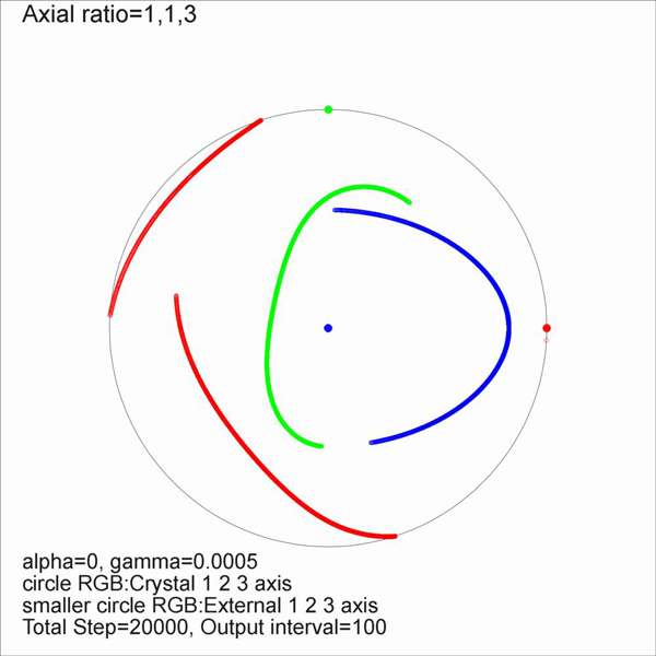
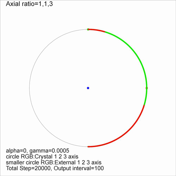
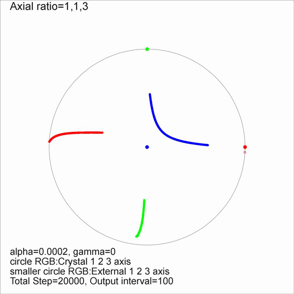
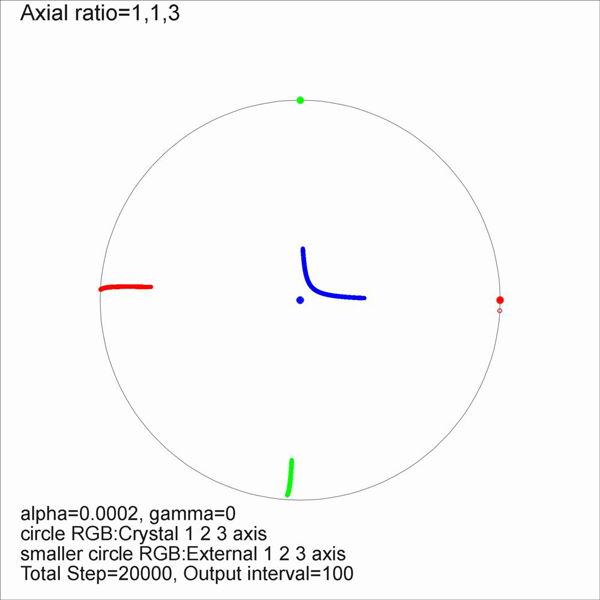
Figure 4 shows the trajectories of the crystal axes on stereograms. For simple shear flow (Figure 4a, b & c), it is shown that no stable orientation of porphyroblast exists. When one of the porphyroblast axis is set parallel to the y' axis (external axis) as the initial condition (Figure 4a & c), the initially y' axis-parallel porphyroblast axis remains stationary. The internal foliation for these cases will be familar ones with the spiral type [e.g. Figure 7.33; Figure 7.37, Passchier and Trouw, 1996]. However, when none of the axes of a porphyroblast are aligned parallel to y' axis (Figure 4b), the porphyroblast keeps rotating while changing its rotation axis. The internal foliation pattern will be more complicated (discussed later). The trajectory of the longest axis (blue in Figure 4b) shows an elliptical pattern, known as Jeffery orbit [Freeman, 1985]. For pure shear flow (Figure 4d, e & f), the longest axis of a porphyroblast approaches to the shear direction. The rotation axis is also changing for these cases (Figure 4d, e & f), but it is expected that the rotation axis will be fixed when the longest axis is parallel to the y' direction. In general, when the porphyroblast axes are inclined to y' axis (or any of the external axes), the rotation axis keep changing its orientation regardless of the geometry of flow until the longest axis become parallel to y' axis for pure shear.
Figure 4. Stereographic projection
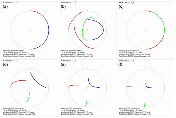
Stereographic projection of the trajectories of rotating crystal axes (axial ratio=1:1:3) at different starting orientations (top row: simple shearing flow, bottom row: pure shearing flow). Details of rotation history for each streogram can be seen in Figure 7. Blue:longest axis (axial lenght=3), Red & Green: shorter axes (axial length=1). Arrows indicate the initial orientation.
When the rotation and growth of algorithm are combined, three dimestional images consisting of volumetric pixels can be constructed (Figure 5 and 6). Figure 5 (a, b & c) shows serial sections cut normal to the external axes (x', y' and z'). The perfect monoclinic symmetry reflecting the monoclinic flow geometry is visible only on the central sections. Details of each experiment, including rotation histories and three dimensional perspective views, can be seen in Figure 7.
Figure 5. Serial sections of a model porphyroblast
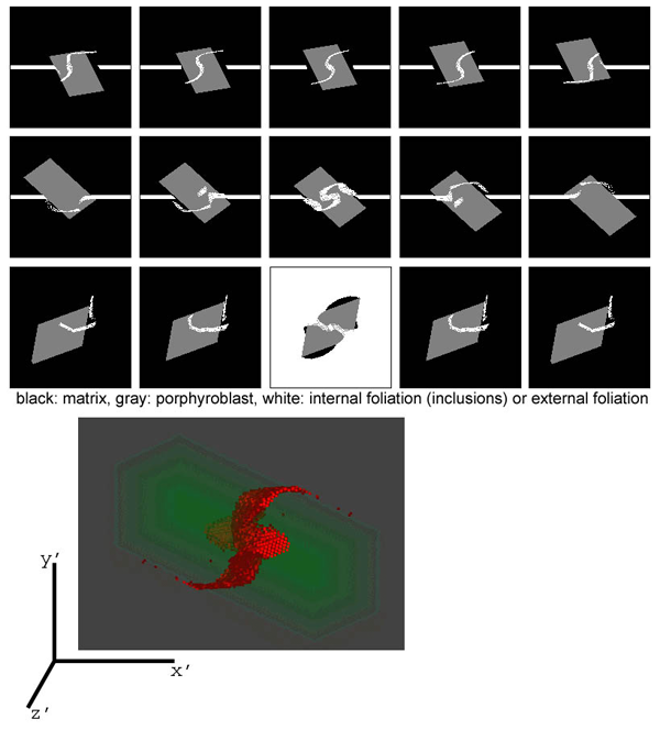
Serial sections of a model porphyroblast with rotation history of Figure 4b (top row: serial sections along the z axis, middle row: serial sections along the x axis, bottom row: serial sections along the y axis).
Figure 6. Perspective views of model porphyroblasts
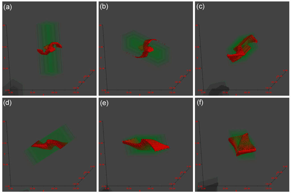
Perspective views of model porphyroblasts with rotation histories in Figure 4 (green: porphyroblast, red: internal foliation). (a) to (f) respectively correspond to Figure 4 (a) to (f).
Animation 1. Animations for crystal rotation and three dimensional view of the inclusion patterns
Animations for crystal rotation and three dimensional view of the inclusion patterns. Figures (a) to (f) respectively correspond to Figure 4 (a) to (f).