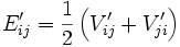
For rotation of porphyroblasts, we have adopted the developed by Jeffery (1922). Details of the mathematical description can also be found in [Jezek et al, 1999]. Figure 1a illustrates the velocity field and velocity gradient tensor (V'ij) with the external coordinate system (x'y'z'). Jeffery derived the sets of equations for rigid objects rotating in a viscous fluid matrix;
where wi represents the angular velocities of an rigid objects around the internal axes (xyz, Figure 1b), and where:
and:
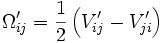
The parameters B1, B2, and B3 which are related to the shape of rigid objects, respectively, represents (b2-c2)/(b2+c2), (c2-a2)/(c2+a2), and (a2-b2)/(a2+b2), and a, b, and c are axes of an ellipsoid object. Description for the orientation of rigid objects can be made much simpler by adopting Euler angles that relate internal coordinate system for rigid objects (xyz) and external coordinate system (x'y'z'). Freeman (1985) provided the solution for the rotation of rigid objects with Euler angles;
and f, q and y represents the Euler angles defined in Figure 1b and the quantities divided by dt represent the rate of changes in three Euler angles.
Figure 1. Velocity gradient tensor and coordinate systems
Velocity gradient tensor and coordinate systems.
Three dimensional velocity gradient tensor (
V'ij) for plane strain deformation in the rectangular coordinate system, x’y’z’.Euler angles between external (x’y’z’) and internal (xyz) reference frames.
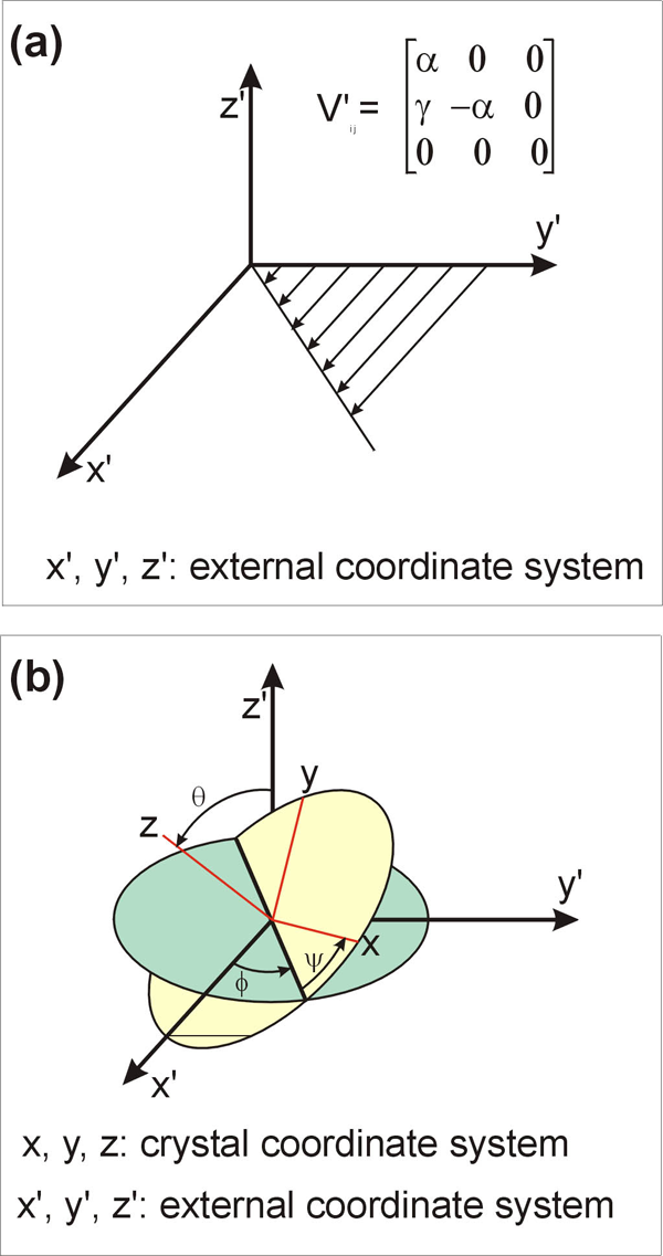
In two dimensions, an area occupied by a crystal with orthorhombic symmetry (a crystal with two sets of mutually perpendicular faces) can be represented with two sets of two parallel lines (Figure 2). If we let (h1k10) to represent the Miller index of a face, the region between the two parallel faces can be described as,
where A is a parameter related to the distance between the face and the origin. Similarly, for another face with the Miller index of (h2k20), the region between these two faces is,
where B is also a parameter similar to A. If a point satisfies the above two inequalities simultaneously, then the point is within the region surrounded by four faces. If we assign larger values for A and B (e.g. new A = old A + growth amount), the region surrounded by the four faces can expand, thus the crystal grows.
For three dimensions, we need three inequalities to define a volume occupied by a crystal with the faces of the Miller indices (h1k1l1), (h2k2l2), and (h3k3l3).
where A, B, and C are parameters related to the distance between the face and the origin. A rectangular-box-shaped porphyroblast can grow by assigning larger values for A, B and C. The shape of the porphyroblast can be determined by relative magnitudes of A, B, and C.
Figure 2. Definition of a crystal surrounded by two sets
Definition of a crystal surrounded by two sets (A1A2A and B1AB2A) of parallel lines. See text for detail.
The data structure for the model (Figure 2) is based on pixels (or volumetric pixels). The pixels within the model system have their coordinate information (x'y'z') and additional material information. The material information for each pixel can be among the following four types;
porphyroblast,
internal foliation within porphyroblast,
matrix,
external foliation within matrix (or future inclusions when they are entrapped).
Development of internal foliation patterns is performed by repeated growth and rotation (Figure 3). During growth, parameters of A, B, and C (described in the earlier section) becomes larger in each step of growth. Depending on the material information, the program replaces matrix with porphyroblast or external foliation with internal foliation as the crystal faces expand. To apply rotation for a porphyroblast, either porphyroblast or matrix can rotate. Here, we have adopted matrix rotation because it is much simpler but still gives the same internal fabric. If pixels have material information of porphyroblast or internal foliation, they remain stationary. On the other hand, pixels occupied by external foliation rotate backward with the amount calculated using Euler angles.
One of the key assumptions made in this study is no dragging of external foliation by the rotation of a porphyroblast. This assumption is physically unrealistic, but we made this assumption because this makes algorithm much simpler and still produces complicated enough textures that may give some insights when interpreting natural textures. Therefore, the results made in this study would be simpler compared with the results made by studies that consider dragging of external foliation [Jezek et al., 1999]. However, these studies also have limitations because of the assumption of Newtonian rheology of the matrix. For successful modelling of natural rocks, a model has to be fully mechanical in order to model non-linear viscous flow in the matrix.
Figure 3. Algorithm for the development of internal foliations
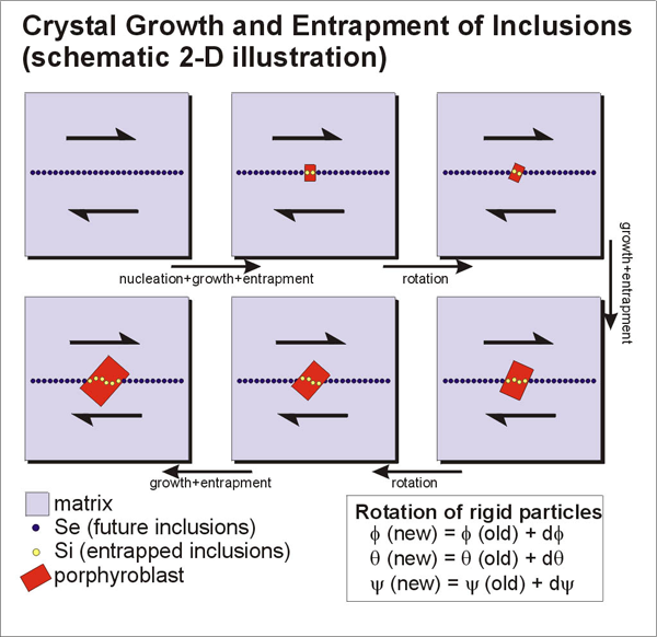
Algorithm for the development of internal foliations.