We developed a two-dimensional discrete element code ("Mike") based on the work of Malthe-Sørenssen et al. (1998) and combined this model with the simulation environment "Elle" [Bons 2000; Jessell et al. 2001, 2003; Piazolo et al. 2001,2002]. The combination of both models allows us to investigate elastic-brittle behavior of complex polycrystalline or layered microstructures. Therefore we can study the influence of microstructural properties on the macroscopic brittle behavior of rocks.
In the discrete element code rigid circular discs or particles are connected with linear elastic springs. Particles are arranged in a triangular lattice so that each particle has a maximum of six neighbors (Figure 1). Such a configuration reproduces macroscopic linear elastic behavior [Flekkoy et al. 2002]. The force acting on a single particle from a connected spring is proportional to the actual length of that spring minus its equilibrium length multiplied by a spring constant. Compressive stresses in the model are thus negative. A particle is in equilibrium when the forces acting on the particle center from different directions cancel out so that the particle has no momentum and will not tend to move. Springs have a predefined breaking threshold that is defined as a critical tensile stress. Once this tensile stress is reached a spring breaks and is removed from the model. The two affected particles that were connected by the spring still have a repulsive force between each other but lack attractive forces.
Figure 1. Six Neighbours
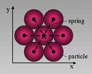
In the discrete element code we use a triangular lattice where each particle is surrounded by six neighbours. Particles are connected by linear elastic springs.
The two dimensional model has the geometry of an initially square area termed the deformation box. Rows of particles on the left and right hand side as well as at the top and bottom of the deformation box are defined as wall-particles (Figure 2). Sidewall and bottom wall-particles are fixed in space perpendicular to the boundary of the box. In order to deform the box wall-particles are moved inwards or outwards to apply compression or extension. Since wall-particles can move parallel to the walls the boundaries do not apply friction. Each time a boundary is moved or a spring breaks in the model a new equilibrium configuration for the lattice is calculated. This is done by a standard over-relaxation method [Allen 1954, Shaw 1953] as described briefly below. In the model each time a wall is moved and the lattice is strained each particle is moved assuming homogeneous deformation. This will remove strain gradients that may result from boundary effects and speeds up the relaxation. Once homogeneous strain is applied the relaxation starts to find a new mechanical equilibrium within the network. Forces on single particles are calculated and particles are moved relative to the resulting force towards their new equilibrium position. In order to attain a more effective relaxation of the whole lattice it is over-relaxed, which means that particles are moved an over-relaxation factor beyond their equilibrium position. This procedure is repeated until a lower threshold is reached that defines the equilibrium of the lattice where particles are stationary. After the lattice reaches force equilibrium the model checks whether or not a spring has reached its critical tensile stress. If this is the case the spring with the highest probability to break will do so and a full relaxation cycle starts again. This procedure is repeated until no more springs break and a new deformation step can start (Figure 3).
Figure 2. Deformation box
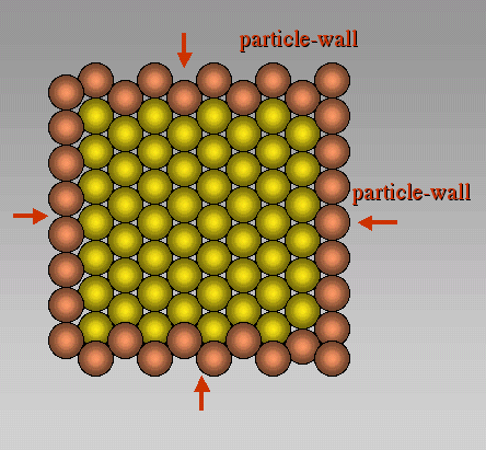
The boundaries or the deformation box are defined by wall-particles. These are shown in brown colour in the figure. Wall-particles are moved in order to strain particles in the box. Wall particles can move parallel to the wall but are fixed perpendicular to it (free slip boundaries). Therefore the walls are frictionless.
Figure 3. Flow of the Program
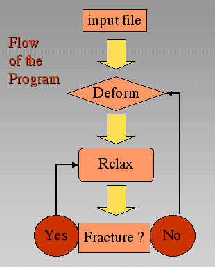
Flow of the Program. First a deformation step is applied on the input structure. After the deformation a relaxation starts in order to find a new equilibrium lattice geometry. Once force equilibrium is reached the program checks if a spring exceeds its tensile strength. If this is the case, the spring with the highest probability to fracture will break and the system is relaxed again. The loop will operate until no more springs fracture. Then the next deformation step is started.
In the "Elle" environment, grains are defined by grain-boundary nodes that are connected by linear elements. In order to combine the "Elle" data-structure with the network of particles in the discrete model the discrete particles present a second layer on top of the "Elle" layer (Figure 4). Particles that lie within an "Elle" grain polygon are defined to be part of that grain. Springs that connect particles of one particular grain will have specific elastic constants and breaking thresholds. Springs connecting two particles of neighbouring grains will have the average spring constant of the two grains and a breaking strength that is characteristic for grain boundaries. In all the presented simulations the grain boundaries are assumed to have a breaking strength that is on average half of the intragranular breaking strength.
Figure 4. "Elle" data structure
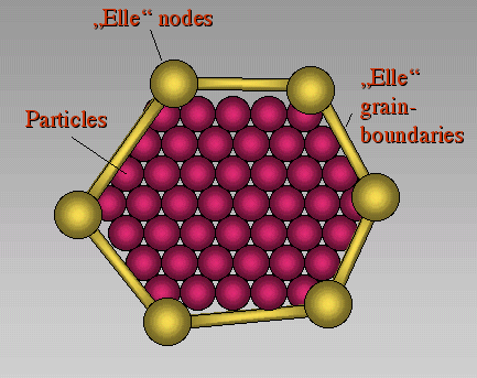
Coupling between the discrete element code and the "Elle" data structure. Elle nodes and connections between these nodes define polygons that may represent grains. Particles that lie within such a polygon are defined to be part of that grain and have the same properties.
Disorder in the system is induced by randomly selecting elastic constants from a Gauss distribution for each grain and randomly selecting breaking thresholds of springs from a linear distribution. Anisotropies in the model can be set by defining layers with different elastic properties. In the presented simulations models consist of 184800 particles for medium resolution and 737600 particles for high resolution. First we will show the development of fractures in a competent layer embedded in a weaker matrix under pure layer parallel extension and compression. Then we will show the development of fractures in polycrystalline materials under pure shear conditions and finally we will discuss fracture patterns around grains that increase in volume. In all simulations we apply a constant strain rate.