As a starting grain fabric, the Elle code uses a set of polygons (called "flynns", Figure 2a) that can, for example, resemble grains in a thin section or an arbitrary designed (poly)crystalline aggregate in two-dimensions. These flynns carry information on the physical and chemical properties of a certain region. The vertices (nodes, Figure 1a) of the flynns can have additional physical and chemical properties. Furthermore, a set of unconnected nodes (called "unodes") can be introduced within the flynns that can be used to describe e.g. chemical variations or varying orientation of crystallographic axes throughout a flynn [Jessell et al., 2001]. All Elle-programs use such a topological description that is saved in a text-file that can be (automatically) translated from standard images (ppm, jpg, gif etc.). To avoid problems due to boundary reflections, the model wraps the boundaries so that the upper and lower and the left and right part are connected.
This data-set can be used to describe physical and chemical properties of a natural rock and the list of properties can easily be expanded as needed. Utilizing the respective physical laws for deformation and/or metamorphism, the data-set can be changed to reflect the evolution of a natural rock resulting from different competing processes. During the simulation, the change of the grain fabric over a certain small increment of time is achieved by moving the nodes of the flynns in small increments and constantly checking the validity of the topology and the correctness of the movement in terms of physical, chemical and geological laws.
The resolution in space is user defined and describes the distance between two or three nodes during the simulations. In Elle this is called the "switch distance" meaning that nodes are inserted or deleted if the distance between two (or three) neighboring nodes falls below or exceeds the switch distance. The switch distance also determines when a neighbor switch occurs when two grains approach each other. If the spacing between two neighboring nodes is smaller than the switch distance or greater than twice the switch distance, an action is taken (delete or insert nodes respectively). Parameters such as physical or geological properties for newly inserted nodes are calculated from the two neighboring nodes. This maintains the desired constant resolution throughout the simulation. The switch distance influences the number of nodes and therefore recursively influences the time needed to simulate any given process. The more nodes in a simulation, the longer the calculations take and vice versa. It is desirable to balance the number of nodes and the required resolution of the simulation so that computation time is minimized. The movement of nodes is calculated with the general equation: Δx = FmΔt where Δx is the incremental displacement vector, F is the driving force vector, m is the mobility and Δt is the time increment. The magnitude of a displacement is thus proportional to the product of mobility and time increment. A change in mobility can thus be regarded as an effective change in Δt. The mobility can be adjusted as needed with values between 10-10 and 10-11. The mobility influences the velocity but not the direction of node movement. In the presented simulations, high ratios of the mobility of boundaries of the melt pockets and the surrounding grains result in a faster movement of the boundary nodes while low ratios of these parameters result in a slower movement (see simulations 4 to 6). However, these values do not influence the final grain fabric so that the solution is stable and accurate enough within the chosen time resolution.
The movement of nodes and hence the change of the grain fabric in the Elle_melt module depends on the relative surface energy of solid-solid and solid-liquid surfaces. If a node movement decreases the free energy of a system, the node will be moved in the calculated direction (if topology-checks allow the movement). The direction of movement is determined in the following way (Figure 2b, see [Bons et al., 2001]): from the current node-position an arbitrary direction is chosen and the change of the total energy is calculated.From this arbitrary direction, 3 orthogonal directions are calculated and the change of the free energy is calculated. The total change in free energy of the system of all 5 positions (4 newly chosen ones and the current node position) is compared and the node is moved in the direction that decreases the free energy of the system the most.
Figure 2. General concept of an Elle file with flynns and nodes
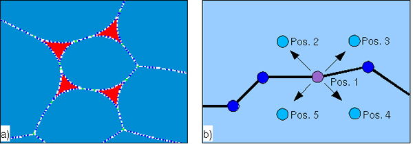
General concept of an Elle file with flynns and nodes. Each flynn and node can hold information on various parameters. In this example, the blue polygons resemble grains and the red polygons resemble melt pockets.
To decide if a node is moved and in which direction, four arbitrary new positions are chosen (Pos. 2 - 5). The resulting decrease or increase of the free energy of each node position (Pos. 1 - 5) is calculated and the position showing the highest decrease of the free energy is chosen.