The growth of stylolites
We will first look at a series of three movies in low resolution that vary in physical size (and thus also in grain size).
Size effects – elastic and surface energies
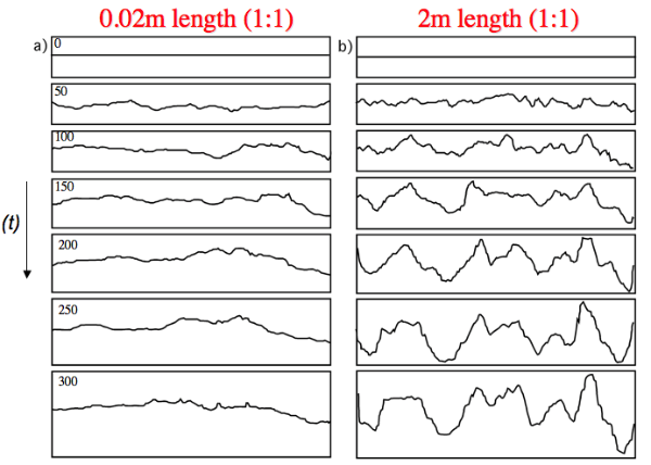
The following simulations use models of low resolution with 100 particles along the horizontal direction so that the individual particles become visible. Dark areas represent the actually dissolved material, the original lattice filled the whole picture. The interface-particles that can dissolve are red. The physical length of the first simulation (Fig. 5) is 10cm so that the grain size would be 1mm. The model contains 5 percent of pinning particles, the pinning particles dissolve half as fast as the host-rock.
Figure 5 and the associated movie illustrate that the stylolite grows relatively fast and develops at least one very pronounced spike or tooth. These structures are typical for the elastic energy dominated growth regime. At the presented settings the transition between the elastic energy dominated and the surface energy dominated regime lies around the mm-scale. This means that as soon as the wavelength of the roughness reaches this scale (about 1 mm) the growth will be dominated by the elastic energy. Since the grain size is already 1mm the stylolite grows in the elastic energy dominated regime from the beginning. Therefore it will develop relatively pronounced teeth. In addition this stylolite has relatively good tracking abilities, it can memorize a large part of the dissolution that took place at the interface. If one compares the length of the spike and the dark area that represents the dissolved material it can be seen that the length of the tooth reflects 50 percent of the dissolved material. One tooth can always only record half of the dissolution at the interface because the interface can fluctuate upwards and downwards. Therefore we can simply double the length of this one spike and retain the full dissolution that happened at the numerical stylolite.
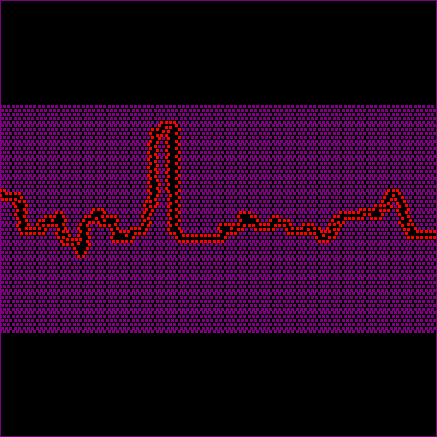
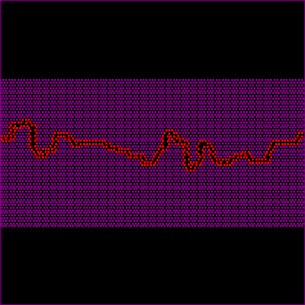
Figure 6 and the associated movie show a simulation that has the same settings as the one shown in figure 5 but with a smaller physical size (1cm length) and also a smaller grain size (0.1 mm). The simulation now starts in the surface energy dominated growth regime. Again the critical wavelength that has to be reached in order to enter the elastic energy dominated regime is about 1mm, or about 10 particles. One can see in the movie (Fig. 6) that the interface is fluctuating in the beginning with more rounded structures. These are typically for the surface energy dominated regime. The growth of the roughness is at first relatively slow. However, after a short while the wavelength of the roughness reaches the mm-scale and grows faster.
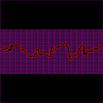
The third simulation (Fig. 7 and associated movie) has an even smaller physical length of 1mm (grain size of 0.01mm). Structures now grow in the surface energy dominated regime for quite a while and the stylolite’s roughness is strongly fluctuating at first. However, even here the wavelength can get large enough to reach the elastic energy dominated regime and the first teeth develop. Compared to the stylolite in figure 6 these teeth are larger. The actual compaction or dissolution is not fully recorded in the teeth in figures 6 and 7.
Scaling regimes and size effects
In order to understand the growth of stylolites in different scaling regimes (surface energy versus elastic energy) we employ methods from statistical physics (Barabasi & Stanley 1995). If we look at the width of a stylolite interface at a given time step in a simulation we first define the mean height as:
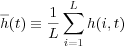
where t is time, h is height of the interface (relative to a reference), L is the system size (number of particles in the horizontal) and i a counter along all particles in the x-direction (Barabasi & Stanley, 1995). The width of the interface for a given time step is then:
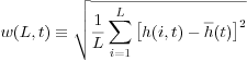
where w is the width of the stylolite as a function of system size Land time step t defined with a RMS (Root Mean Square) function. h is the height of point i on the interface and it is subtracted by the mean height to get the real width. We can now calculate the width of the interface for the different time steps of the model run and study the growth of the interface with time. From statistical physics we know that for such interfaces growth can be best observed in log/log space plotting log of w against log of t (width against time). Typically these interfaces show a linear growth regime in log/log space with a characteristic growth exponent β until they reach a wavelength that interferes with the system size, the growth saturates and the amplitude of the interface becomes constant (Barabasi & Stanley, 1995; Koehn et al., 2007; Ebner et al., 2009).
Figure 8. Different growth regimes of roughening interfaces in log/log space (interface width versus time).
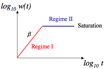
The two regimes can be defined as:
Regime I: w(L,t) ~ tβ
Regime II: w stays constant
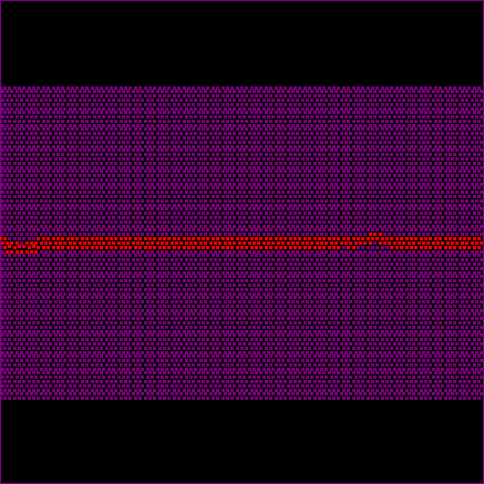
In Regime I the growth follows a power-law with a growth exponent β, whereas in Regime II the growth saturates and the stylolite loses its memory for compaction. The growth exponent β changes between different stylolites, it can vary from 0.5 (strongly non-linear growth) in the surface energy dominated growth regime to 1.0 (linear growth) when large fossils or grains pin the interface. Variations of this exponent are illustrated in Koehn et al., 2007 and Ebner et al. 2009, with 0.5 to 0.6 for the surface energy dominated regime and up to 0.8 for the elastic energy dominated regime. In addition the critical time when saturation of the interface can be reached varies between different stylolites. The saturation as a function of system size can only be reached when the stylolite has a restricted length, which is the case for the simulations. However, bedding parallel stylolites may not have a real system size in reality (or they have a very large system size). In addition different growth regimes change the critical time for saturation, so that saturation can be reached relatively early in the surface energy dominated growth regime but may not be easily reached in the elastic energy dominated regime. The following two simulations illustrate some of these effects. The only difference between the simulations shown in figures 9 and 10 and the associated movies is the real physical size. The stylolite shown in figure 9 has a real physical length of 0.02 m (grain size 50 mm) and developed with an average normal stress of 10 MPa. Lower stresses (10 versus those stylolites with 40 MPa) means that the surface energy dominated regime is active at larger sizes since the elastic energy is lower if the stress is lower. The stylolite shown in figure 9 and the associated movie has no pronounced teeth or spikes and contains very low amplitude wavelengths. The movie illustrates that the amplitude is reached relatively fast during the growth process and that it does not change through most of the stylolite development. The wavelength is just fluctuating. This is exactly what happens when the saturation time is reached. Dissolution is still happening at the interface but the amplitude does not grow, the stylolite has lost its memory of compaction (or dissolution).
Simulation 9. Simulation with a high resolution (400 particles in x direction) illustrating surface energy dominated growth.
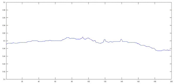
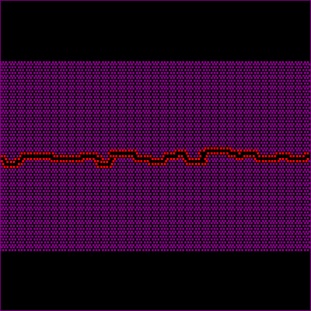
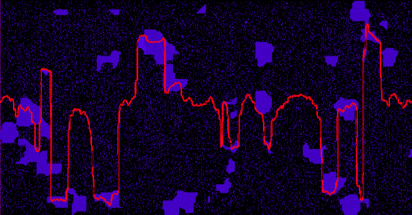
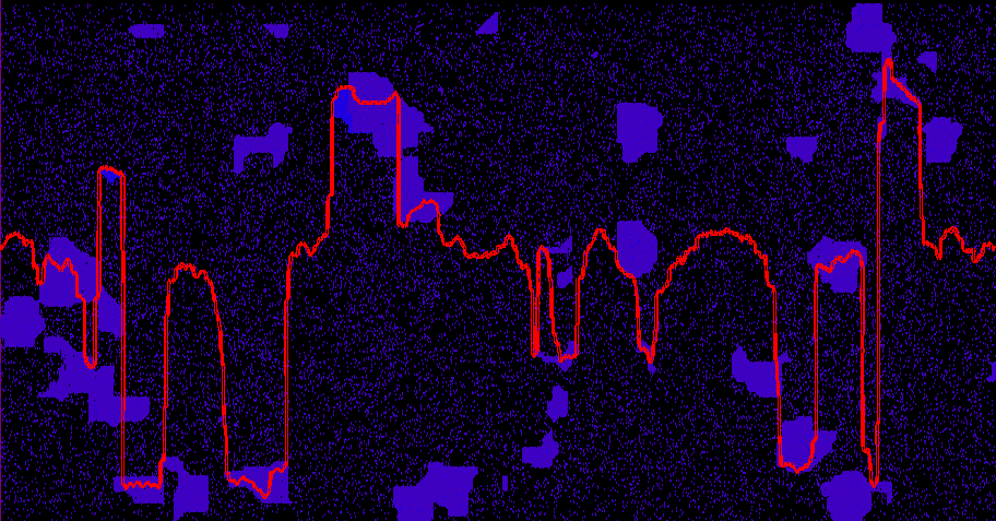
Figure 10 shows a simulation with the same settings as the one shown in figure 9 but with a larger physical length of the stylolite (initially 2m) and a larger grain size of 5mm. Figure 10 already illustrates that this stylolite reaches the critical wavelength and grows pronounced teeth and spikes. The associated movie shows that the initial growth of both stylolites (small and large) is relatively similar but the larger stylolite continuous to grow and develops teeth whereas the small stylolite saturates.
Simulation 10. Simulation with a high resolution (400 particles in x direction) illustrating elastic energy dominated growth.
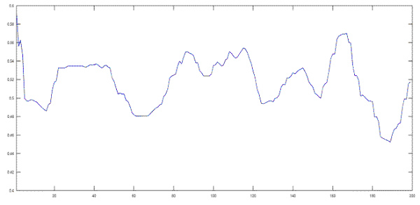
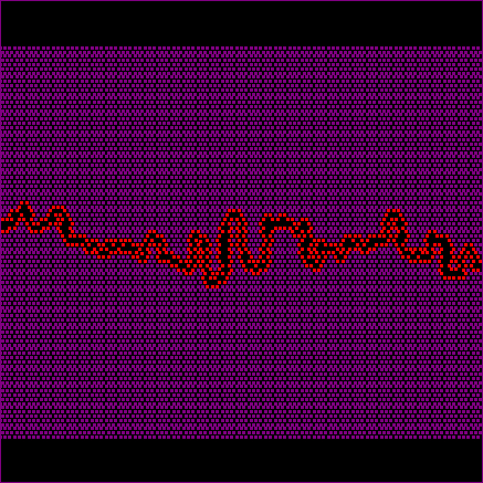
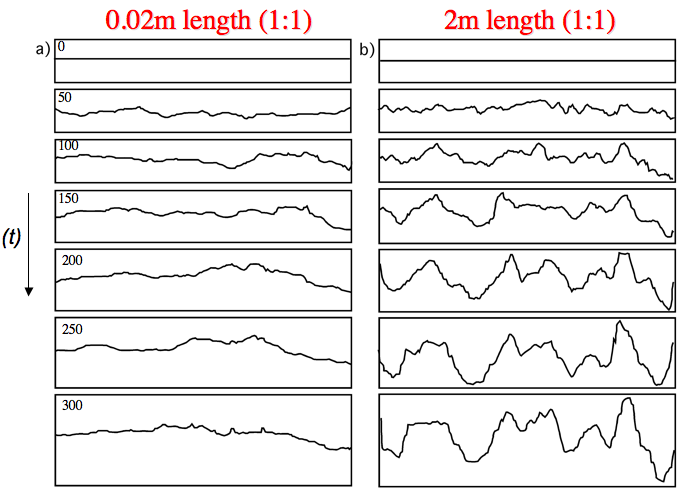
Figure 11 shows both stylolites next to each other for different growth steps. One can see that at step 50 the stylolites still look a bit similar whereas from step 100 onwards the small stylolite already stops growing, whereas the large one starts to produce nice teeth and spikes.
Figure 11. Snapshots of the two stylolite simulations shown in figures 9 and 10.
The stylolite on the left hand side is just fluctuating whereas the one on the right hand side develops pronounced teeth and spikes.
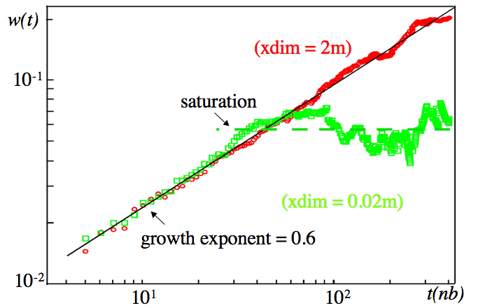
Finally we can plot these two simulations in log-log space showing log of the mean width of the stylolites versus log of the time steps in the simulations (Fig. 12). Both plots in figure 12 show that the small and the large stylolite grow with a similar growth exponent of 0.6, so the growth is slow and non-linear. The small stylolite saturates relatively early, the mean width is just fluctuating around a constant value after time step 30 to 40. The large stylolite continues to grow and does not reach saturation.
Figure 12. Plot of the log of the mean width of stylolites shown in figures 9 and 10 versus log of modelling steps.

The small stylolite (green dots) shows both growth Regimes (I and II) whereas the larger stylolite (red dots) shows only powerlaw growth (Regime I) and no saturation (see also Koehn et al., 2007; Ebner et al., 2009).
Pinning variations
In the previous chapters we have seen how elastic and surface energies can influence the growth and appearance of stylolites. However, the shape of the stylolite is also strongly influenced by the nature of the noise or pinning particles. This is illustrated in the following simulations. In the first three simulations a variation of the amount of pinning particles (0.5 to 20%, normally 5%) and of their pinning “strength” are presented followed by one example of a bimodal grain size. Pinning has three parameters, the size of the pinning particles (as seen in previous chapters), the amount of pinning particles (0.5 to 20%, normally 5%) and the pinning “strength”. In the simulations the pinning “strength” is defined by the amount the pinning particles dissolve slower than matrix particles. In previous simulations the pinning particles dissolved half as slowly as the matrix and 5% of the particles where pinning. The following three simulations have a mean average stress of 40 MPa and an initial stylolite length of 10cm. The first simulation (Fig. 13) has a “normal” pinning strength but only 0.5% of particles pin. This leads to no significant pinning, the surface remains flat throughout the simulation.
The second simulation (Fig. 14) shows a simulation with 20 percent of pinning particles but a very low pinning strength. Pinning particles only dissolve by a factor of 0.9 slower than normal particles. This pinning strength is enough to produce a roughness, however this roughness is easily destroyed so that the roughness growth is very slow.
Finally the third simulation (Fig. 15) shows the growth of a stylolite with 20 percent of pinning particles and the normal pinning strength. Now the roughness develops very quickly with pronounced spikes and teeth. The simulations shown in figures 13 to 15 clearly illustrate that the pinning can have a pronounced effect on the shape of the developing stylolite. However, Ebner et al. (2009) showed that the pinning strength and the amount of pinning particles does not have a strong effect on the scaling properties of the stylolites, including their growth exponents. There are only significant changes in some extreme cases. Most of the changes are directly linked to the grain size and thus the pinning size, which was discussed in the first chapters.
Bimodal grain size (or fossils)
The last simulation uses the highest resolution of 800 times 940 particles (752,000 particles in the mesh) and shows a bimodal noise with 5 percent of small pinning particles and 5 percent of larger grains (defined by clusters of particles) that also pin (Fig. 16). The length of the initial stylolite is 8cm, the average stress is 40 MPa.
The small grains (grain size 0.1mm) produce a roughness that is similar to that of figure 6 whereas the large grains (grain size about 4mm) produce pronounced teeth like the simulation shown in figure 5. Therefore it can be clearly seen that figure 16 is a combination of two grain sizes (those shown in figures 5 and 6) that produce growth in very different regimes, the small grain size in the surface energy dominated regime fluctuates and grows slowly, whereas the large grain size, in the elastic energy dominated regime, grows fast and produces pronounced spikes and teeth. The stylolite, as such, is dictated by the larger grain size; these grains produce the nice peaks and record the compaction (dissolution).