VII. GEOLOGIC MAPPING OF THE SANCTUARY
VII-A. Introduction
My geologic mapping of the study area was carried out during two weeks in the summer of 2004, two weeks in the summer of 2005, and four weeks (each) in the summers of 2007, 2008 and 2009. The scale of mapping was ~1:6000, using as base maps space-satellite imagery and topographic maps (contour interval 4 m). I recorded observations at ~800 stations, with attention given to identification of formation(s), rock type(s), geologic structures, and orientations of bedding, folds, and faults, and in certain instances joints and (rare) cleavage. I shot abundant digital photographs of the geology in order to assure a comprehensive descriptive record. Orientation and location data were recorded in an Excel file, and ArcMAP was used to fashion geological map products for GIS analysis and interpretation.
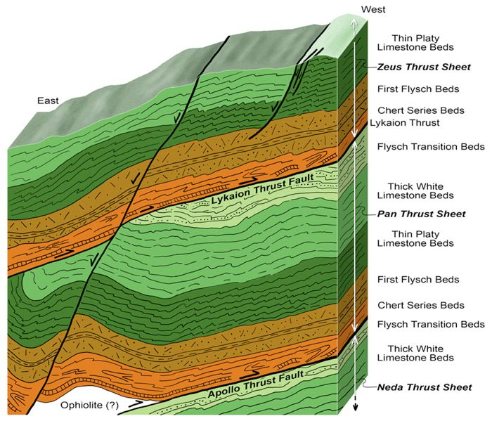
My geological map of the Sanctuary of Zeus study area is presented as Figure 21. In addition I created a “geostructural column” to portray the basic structural geologic relations within the Mt. Lykaion map area (Figure 22). The geostructure column, among other things, distinguishes relationships in the western two-thirds of the area (“west domain”) and the eastern one-third of the area (“east domain”). The pivotal structural feature in the area overall is the Lykaion thrust.
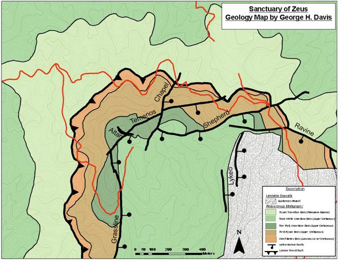
Figure 21. Geologic map of the Sanctuary of Zeus, Mt. Lykaion.
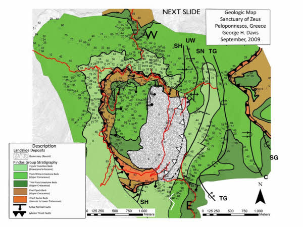
Mapping by George H. Davis, with field assistance from Tom Fenn, Randy Goosen, Phil Nickerson, and Karl Yares.
Figure 22. Schematic picture of structural geology of Mt. Lykaion study area.

This ‘geostructural column’ diagrammatically summarizes the fundamental structural relations and properties derived from the geologic mapping. Note that two domains are specified, labeled “west” and “east.”
VII-B. West Domain Faulting and Folding
VII-B1. Overall Structural Relationships.
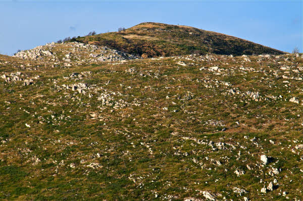
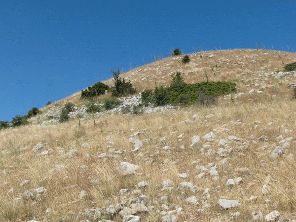
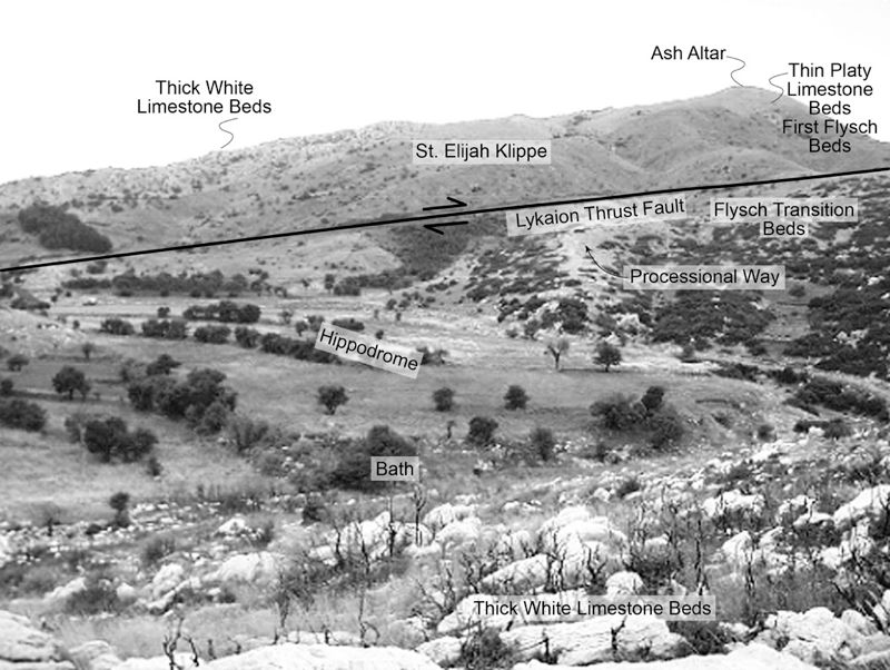
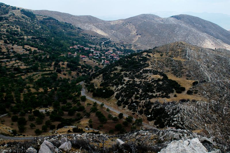
The singularly distinctive geologic map pattern in the western two-thirds of the area expresses the presence of a roughly elliptical, closed-loop trace of a major subhorizontal thrust fault (see Figure 21), which I have named the “Lykaion thrust fault.” Its expression in the landscape is pronounced (Figure 23). Immediately above the fault is an ascending stratigraphic succession of four of the five mappable formations, namely the Chert Series Beds, First Flysch Beds, Thin Platy Limestone Beds, and Thick White Limestone Beds, all in proper stratigraphic order (see Figure 23). Below the Lykaion thrust is Flysch Transition Beds resting on top of a descending stratigraphic succession of Thick White Limestone Beds, Thin Platy Limestone Beds, First Flysch Beds, and Chert Series Beds, again in proper stratigraphic order. The geological mapping reveals quite clearly a concentric elliptical pattern of the distribution of the Pindos Group formations (see Figure 23).
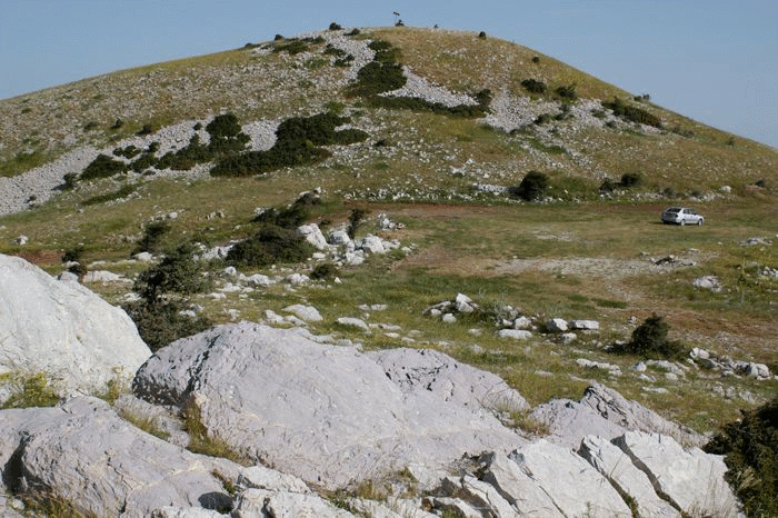
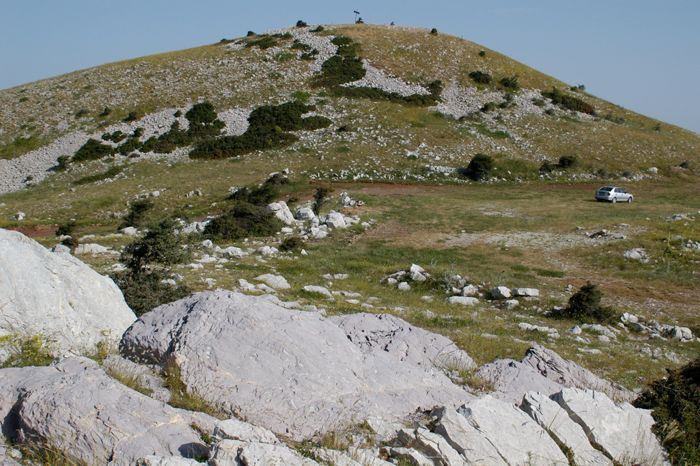
Figure 23. View of Sanctuary of Zeus from the north.


B. Annotated rendition, with identification of some of the rock formations, structures, and archaeological elements.
The Lykaion thrust fault, therefore, is a structure that marks a boundary between two thrust sheets of the Pindos stratigraphic formations. The upper sheet, exposed in the western two-thirds of the area, is a tectonic “klippe” (see Figure 23). It is composed of upper thrust sheet formations tectonically transported over lower thrust sheet formations that were once laterally removed, in all probability, by several kilometers or more. Subsequent to the thrust faulting, the upper thrust sheet rocks were partially removed, through erosion, to leave Mt. Lykaion as an isolated klippe (Figures 24). For reference I have named the klippe the “St. Elijah” klippe (after “Agios Elias,” the mountaintop saint); the upper thrust sheet, the “Zeus thrust sheet;” and the lower thrust sheet, the “Pan thrust sheet.” At the base of the Pan thrust sheet is another thrust (see Figure 22), which I have named the “Apollo thrust fault,” whose trace expression lies just outside of (west of) the Mt. Lykaion map area proper. (I believe that this thrust fault might pass close to the Temple of Apollo at Bassi). Its presence is quite clear, with Chert Series Beds (above) faulted upon Flysch Transition Beds (below). The thrust sheet beneath the Apollo thrust fault is here called the Neda thrust sheet.
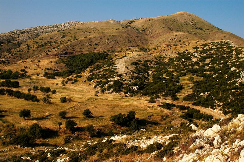
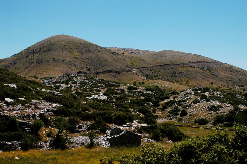
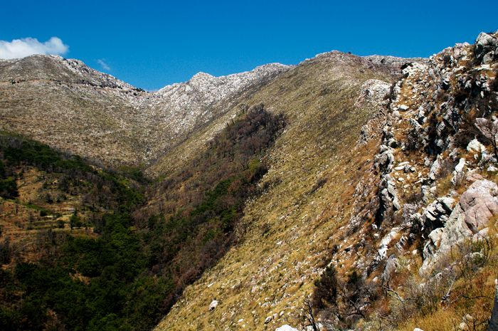
Figure 24. View of the St. Elijah klippe from the west.

This is a view from the northwest side of Agios Elias. In the foreground is terrain underlain by limestone (Thick White Limestone Beds and Flysch Transition Beds), belonging to the Pan thrust sheet. The location of the Lykaion thrust is where the uppermost part of this limestone terrain gives way to smooth slopes lacking obvious bedrock. Above the thrust is the Zeus thrust sheet. Near the base of it are smooth slopes underlain by Chert Series Beds and First Flysch Beds. Thin Platy Limestone Beds can be seen in the distant background, at the top.
An imperfect bulls-eye distribution of Thin Platy Limestone Beds and Thick White Limestone Beds is evident at the top of Mt. Lykaion (see Figure 21). The complexity of the map pattern in this particular part of the area is due to moderate- to high-angle normal faulting of rocks within the Lykaion klippe. These faults juxtapose First Flysch Beds, Thin Platy Limestone Beds, and Thick White Limestone Beds in abrupt and angular, compartmentalized patterns. The nature and significance of this faulting will be described below in section VII-D.
VII-B2. Orientation of Lykaion Thrust, and the Thrust Sheets
The orientation of the Lykaion thrust fault underlying the St. Elijah klippe was determined through three-point methodology applied to the fault contact separating Chert Series Beds (above) and Flysch Transition Beds (below) (see Figures 21 and 22). The solution yielded a strike of N33°E and a dip of 10°SE. Thus this thrust fault within the west domain is very gently inclined, consistent with the observation that the apparent dip of the thrust in places is very close to horizontal (see Figures 23 and 24).
Within the Pan thrust sheet, and thus beneath the Lykaion thrust fault, the overall orientation of the stratigraphic formations seems best reflected in the stratigraphic contact between Flysch Transition Beds (above) and Thick White Limestone Beds (below) (see Figures 21 and 22). Three-point determination of this contact yielded a strike of N37°E and a dip of 5°SE. The orientation of the Lykaion thrust compares favorably with the orientation of the plane of best fit to the upper faceted surfaces of the corrugated landforms underlain by Flysch Transition Beds just beneath the thrust (see Figure 20C). In particular, three-point methodology applied to the tops of the corrugations resulted in a N22°E, 2°SE solution, which is an orientation essentially parallel to the attitude of the Lykaion thrust fault.
Within the St. Elijah klippe (i.e., within the Zeus thrust sheet) the apparent overall macroscopic orientation of stratigraphic units appears best expressed in the map pattern of the base of the First Flysch Beds, where these beds are in contact with the top of the Chert Series Beds (see Figure 21). This lower contact of First Flysch Beds can be traced without interruption around the full extent of the northern and western flanks of the St. Elijah klippe. A three-point determination of the attitude of this contact reveals that it strikes N35ºE and dips 8ºSE. It is this orientation that is used as the basis for constructing the dip inclinations of the major stratigraphic units above the Lykaion thrust fault, as shown in Figure 22.
VII-B3. Analysis of Bedding Attitudes in the Pan Thrust Sheet
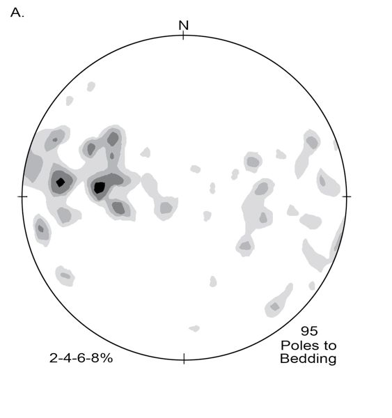
Further structural analysis was helpful in reconciling the overall gentle structural and stratigraphic orientations with the significant range of strike and dip variability within each of the mapped formations. Data were plotted stereographically using the Rockware StereoStat software program developed and written by Stephen Ahlgren. The most revealing plots are contoured lower-hemisphere equal-area projections of all poles to bedding in the Pan versus Zeus thrust sheets (Figure 25). For bedding orientations measured in the Pan thrust sheet, the contour plots feature great-circle girdles along which two modes of pole concentrations are evident. We see this in the composite diagram (see Figure 25A), which shows contoured poles to bedding attitudes measured in Thin Platy Limestone Beds, Thick White Limestone Beds, and Flysch Transition Beds in the Hippodrome thrust sheet. The dominant modal concentration (I) reflects an average orientation of N20°E, 35°SE, and the subordinate modal concentration (II) reflects an average bedding orientation of N10°W, 40°SW.
Figure 25. Stereographic projections of poles to bedding, Pan plate and Zeus plate.
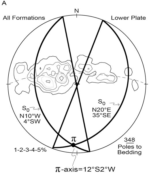
A. Lower-hemisphere equal-area stereographic projection of poles to bedding in the Pan thrust sheet in the West Domain of the map area. Contours are percentage of total data points falling within each 1% area of the net. The number of measurements are as follows: Thin Platy Limestone Beds, 18; Thick White Limestone Beds, 141; and Flysch Transition Beds, 179.
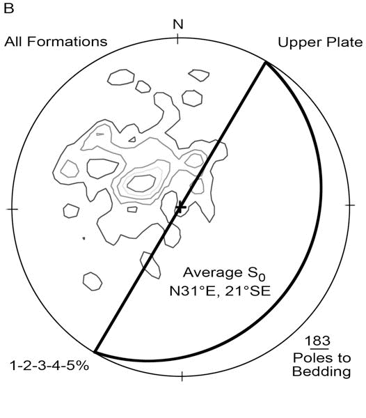
B. Lower-hemisphere equal-area stereographic projection of poles to bedding in the St. Elijah klippe. This is a composite plot for all measurements within the Chert Series Beds (31), First Flysch Beds (34), Thin Platy Limestone Beds (42), and Thick White Limestone Beds (62).
The dominant modal concentration for bedding strike in the Pan thrust sheet (i.e., N20°E) departs approximately 15° counter-clockwise from the strike orientations determined through three-point methodology (N35°E, N33°E, and N37°E) for First Flysch Beds in the St. Elijah klippe, the Lykaion thrust fault, and the stratigraphic contact between Flysch Transition Beds and Thick White Limestone Beds in the Pan thrust sheet. The dip inclination reflected in the dominant modal concentration (i.e., 35°SE) is slightly steeper than the dip determinations derived through three-point methodology for the dip of the thrust (i.e., ~10º SE), and the mapped formations in the Zeus thrust sheet (ranging from ~8º to ~30ºSE) and in the Hippodrome sheet (~5ºSE). The subordinate modal concentration (N10°W, 40°SW; see Figure 25A) seems to reflect the average orientation of short limbs in the westward-verging asymmetrical folds within the Pan thrust-sheet formations. The girdle of points, overall (see Figure 25A), is a p-circle consistent with folding about a modal fold-axis orientation of 12°S, and a modal axial-surface orientation of N-S, 90º. The combination of the analysis of map patterns and the stereographic projections reveals that the various Pan thrust sheet formations are not, together, folded into large anticlines and synclines. Instead, each formation has retained an overall tabular appearance and orientation, with the folds relatively small in size and embedded within each major stratigraphic unit. Thus the picture is one of disharmonic folding (see Figure 22).
VII-B4. Analysis of Bedding Attitudes in the Zeus Thrust Sheet
Figure 25B is a lower-hemisphere stereographic projection of all poles to bedding for measurements taken within the Zeus thrust sheet, in Chert Series Beds, First Flysch Beds, Thin Platy Limestone Beds, and Thick White Limestone Beds. No great-circle distribution of poles to bedding is evident, but instead there is a single modal concentration, reflecting a dominance of homoclinal inclination of bedding. The unimodal concentration coincides with an overall average strike and dip orientation of N31°E, 21°SE. The average strike orientation corresponds closely to the strike value determined by three-point methodology for the lower contact of the First Flysch Beds (N35°E) in the Zeus thrust sheet within the St. Elijah klippe, the strike of the Lykaion thrust fault (N33ºE), and the stratigraphic contact between Flysch Transition Beds and Thick White Limestone Beds (N37°E) in the Pan thrust sheet. However, the measured orientations of bedding dip tend to be steeper on average (i.e., 21°SE) than the overall dip of First Flysch Beds in the St. Elijah klippe (8°SE), the dip of the Lykaion thrust fault (10°SE), and the dip of the stratigraphic contact between Flysch Transition Beds and Thick White Limestone in the Pan thrust sheet (5°SE).
Finer analysis of bedding orientations for each of the formations within the St. Elijah klippe integrate into what appears to be a steady, systematic counter-clockwise shift in average strike orientation, by formation, down-section through the St. Elijah-klippe stratigraphy toward the Lykaion thrust. The youngest formation is Thick White Limestone Beds, and the average orientation of bedding within this formation is N65°E, 30°SE. Stratigraphically beneath this formation in the St. Elijah klippe is the Thin Platy Limestone Beds, and its bedding attitude averages N40°E, 20°SE. Deeper still is First Flysch Beds, with an average bedding orientation of N20°E, 30°SE. For the Chert Series Beds, immediately above the Lykaion thrust fault, the average bedding orientation is N26°E, 23°SE.
The counter-clockwise shift in strike of bedding (progressively) downward in the St. Elijah klippe suggests that the thrust-shearing associated with tectonic transport of the Zeus thrust sheet had the effect of ‘streamlining’ bedding orientations, formation by formation, toward closer parallelism with the strike attitude of the Lykaion thrust fault. The N65°E average strike of the Thick White Limestone Beds, which is furthest above the Lykaion thrust, departs most significantly from the N33°E strike of Lykaion thrust fault.
VII-B5. Analysis of Outcrop-Scale Folds in the Thrust Sheets
Analysis of folds in Thin White Limestone Beds within the Pan thrust sheet was based upon field work, stereographic analysis (see Figure 25), examination of photographs of outcrop-scale folds for which measurements were taken, and study of notes of limb-dips of these folds, Folds within the unit are essentially symmetrical, with ‘synthetic’ limbs (i.e., dipping in the same direction as the Thin Platy Limestone Beds as whole) striking N5°E and dipping 35°SE, slightly more steeply than the overall formation. The stereographically determined modal axial plane orientation for these data is essentially north-south striking and vertical.
The stereographic features within the pole diagrams for bedding within the Thick White Limestone Beds and the Flysch Transition Beds reveal what can be seen in outcrop. The dominant folding is asymmetric intraformational folding marked by relatively long synthetic limbs dipping in the same direction (though more steeply) as the overall formation attitude, and by relatively short antithetic limbs dipping in the opposite direction to the overall inclinations of these formations. The average fold-axis orientation is identical for each of these formations. The stereographically determined modal fold axis orientation for each is 10° S2°E. The angle of fold-axis plunge (10°) is thus very close to the average dip (5°) for the formations viewed macroscopically, revealing that the fold hinges are not only contained within the formation but have axes that are coplanar with the overall attitude of the formation. There is also a close similarity in orientation between the dominant (synthetic) limb mode (I) seen stereographically for the Thick White Limestone Beds (N15°E, 35°SE), and that of the Flysch Transition Beds (N12°E, 30°SE). Furthermore, there is a reasonably close correspondence in attitude between the secondary (antithetic) limb mode (II) for these same two formations (N19°W, 35°W for Thick White Limestone Beds; N9°W, 43°W for Flysch Transition Beds). Axial-surface orientations of the fold structures in all three of the formations are the same, namely NS-striking and dipping essentially vertically.
The physical manifestation of geometric measurements is a reasonably penetrative fold pattern marked by asymmetry. The asymmetry is one marked by a distinct westward fold vergence, which is consistent with tectonic transport by thrusting generally from east to west. This direction of transport is well documented regionally for the Pindos fold and thrust belt. Moreover, the fold-axis orientations (essentially due south) are consistent with an interpretation that here, within the sanctuary, the tectonic transport was truly from due east to due west. This interpretation is further confirmed by the presence of crystal-fiber lineations on shear surfaces seen in limestone outcrops in the Pan thrust sheet that show a preferred orientation essentially east-west. Furthermore, stereographic plotting of a number of hinges of outcrop-scale fold structures shows a preferred orientation of N-S, i.e., at right angles to direction of tectonic transport.
In some ways the most interesting observation from fieldwork and fold analysis is that the various formations in the west domain within the Pan thrust sheet are not, together, folded into large anticlines and synclines. Instead, each formation has retained an overall tabular appearance and orientation, with the folds relatively small in size and sandwiched intraformationally within each major stratigraphic unit. Thus the picture is one of disharmonic folding (see Figure 19). It would appear that internal to each formation the fold attributes are driven by the standard controls for free folding: strength contrasts between mechanically stiffer and softer layers, and thicknesses of stiff layers. It would appear that the driving mechanism is layer-parallel (thrust) shearing. If this is true, the fold properties may be a guide to estimating shear strain magnitudes within each of the formations within which folding is penetrative. It is probable that the pervasive outcrop-scale folding largely represents layer-parallel shortening before the onset of major folding and thrusting.
VII-C. East Domain Faulting and Folding
VII-C1. Overall Structural Relations
The eastern third of the map area contains a system of major folds, and these reside in the Pan thrust sheet (see Figures 21 and 22). The folds are westward-overturned anticlines and synclines, which trend north-south and plunge at very low angles. Also in the east domain is another exposure of the Lykaion thrust fault, which dips ~25°E and places Chert Series Beds in the immediate hanging wall upon Thick White Limestone Beds on the immediate footwall (see Figure 21). The Chert Series Beds is generally poorly exposed here, not only because of the incompetence of the lithologies, but because the Chert Series Beds formation has been thinned and locally eliminated through thrust-related shearing.
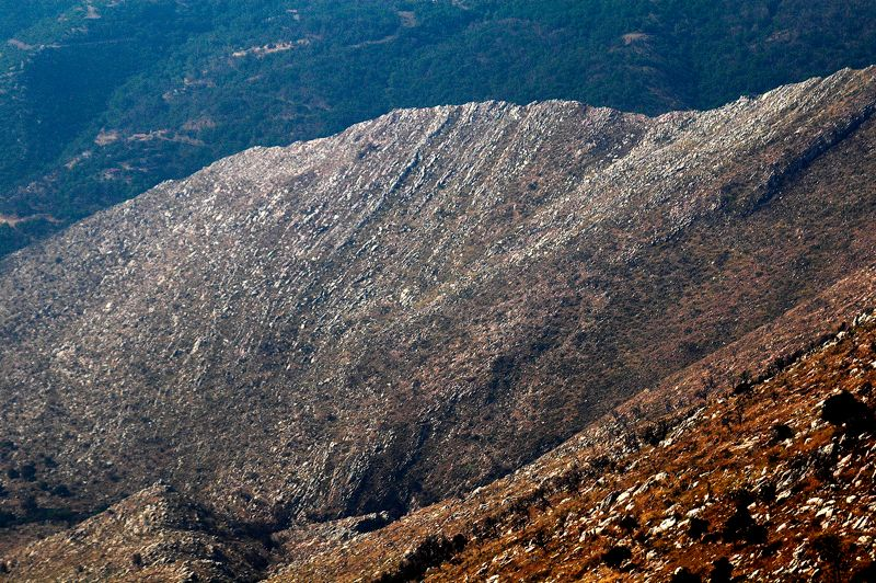
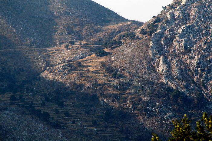
The location of the exposure of the Lykaion thrust fault in the east domain stands out boldly, for the dark-colored hanging wall strata contrasts strikingly with the white footwall strata (Figure 26). Sandstones within the First Flysch Beds in close proximity to the Lykaion thrust fault are strongly fractured and faulted (Figure 27A). Some ancillary thrust surfaces stand out as distinctly smooth and planar (Figure 27B). Before erosion to create Mt. Lykaion as we see it today, the (Lykaion) thrust fault exposed along the eastern margin of the map area was co-extensive with the thrust fault surface beneath the St. Elijah klippe to the east.
Figure 26. East-view of Lykaion thrust fault, placing dark on light.
East-directed photograph of exposure of Lykaion thrust fault in the east domain of the map area. The thrust is “black on white.” The white limestone outcrops in the foreground belong to the Thick White Limestone Beds formation within the Pan thrust sheet. The dark outcrops at the summit belong to the Chert Series Beds and First Flysch Beds, and comprise a part of the Zeus thrust sheet.
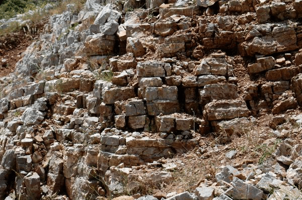
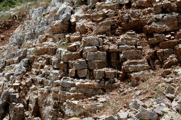
Figure 27. Thrust fault damage within First Flysch Beds.
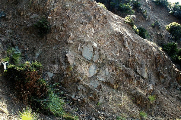
A. Photograph of faulted, fractured sandstone of the First Flysch Beds near the Lykaion thrust fault.

B. Photograph of a discrete fault surface within First Flysch Beds near the Lykaion thrust fault proper.
This thrust exposure represents a deeper level of thrust faulting than what is evident along the base of the St. St. Elijah klippe, because Flysch Transition Beds are missing. Chert Series Beds rests in fault contact on Thick White Limestone Beds. In contrast, along the base of the St. St. Elijah klippe, Chert Series Beds rests on Flysch Transition Beds (see Figure 21). This difference is consistent with the interpretation that the direction of thrusting was from east to west (Peter DeCelles, 2008, personal communication).
Macro-folding is the dominant structure in the east domain. The expressions of folds in the landscape are magnificent! There are six major fold structures (see Figure 21), named here (from west to east) the Sheep Herder’s syncline (after permanent sheep station in south part of map area), the Upper Walnut anticline (after the village of “Ano Karyes”); the St. Nicholas syncline (after “Agios Nikolaus”); the Three Gorges anticline (after “Tria Remmata”); the Cretea syncline (one limb of which projects to Cretea ridge), and the St. George anticline (after “Agios Georgios”). The southern part of the Upper Walnut anticline and much of the Sheep Herder’s syncline are covered by extensive landslide deposits (see Figure 21). The St. Nicholas syncline is well exposed near a tiny chapel of the same name. Part of its expression is the strike ridge of Thick White Limestone Beds that trends north-south just east of the village of Ano Karyes (see Figure 21). The continuity of strike ridges within this fold is broken by east-west-trending compartmental faulting, which has produced right-lateral strike-slip separations of tens of meters (Figure 28; see also Figure 21).
Figure 28. Compartmental faulting evident along strike ridge.

North-directed view of strike ridge of Thick White Limestone Beds, which here define part of the overturned east limb of the St. Nickolas syncline. Note how “compartmental faults” at right angles to the strike ridge cause abrupt offset of the limestone bedrock. The shifts tend to be right lateral. The overall effect is obvious when comparing the location of the western boundary of the marker unit in the lower left corner of this photo, versus the location of this same horizon off in the distance. The village of Ano Karyes lies in the background; this, our home for the project. Also note that in the far distance (back right), the expression of rocks in the landscape reveal the location and orientation of the Lykaion thrust fault (also pictured in figure 26). The dark-weathering bedrock in back right is the Zeus thrust sheet. The light-weathering bedrock is the Pan thrust sheet.
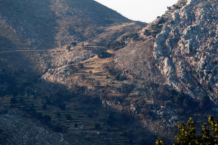
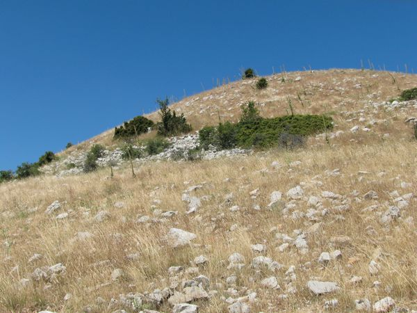
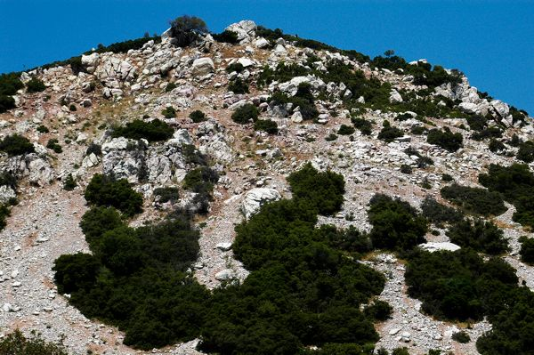
Figure 29A captures the elegance of the Three Gorges anticline. The fold at this location is expressed in the weathered landscape expressions of the First Flysch Beds, Thin Platy Limestone Beds, and Thick White Limestone Beds, respectively. The ground distribution of First Flysch Beds is revealed by the dense cover of trees, accentuated because the trees were charred by intense wildfires during August, 2007. The brown sandstone lithologies that comprise the First Flysch Beds apparently favor soil development conducive to tree growth. Thin Platy Limestone Beds overlies the First Flysch Beds and is marked by its characteristic grassy and blocky landscape appearance (see Figure 29A). Stratigraphically above Thin Platy Limestone Beds are Thick White Limestone Beds. This formation is distinguished in the landscape by jutting, craggy outcrops topped by wiry bushes and trees, which at this location were significantly diminished by the wildfires (see Figure 29A). Thus, the landscape expressions of these three distinctive formations ‘track out’ the form of the overturned anticline!
Figure 29. Three Gorges anticline.
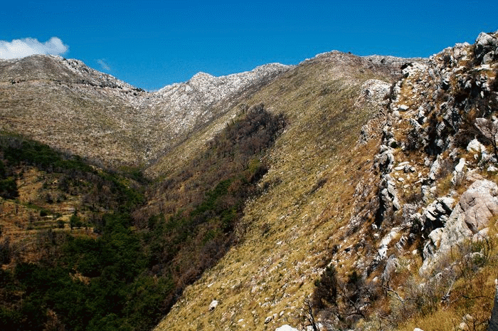
A. The form of the Three Gorges anticline can in places be seen in the landscape expression of bedrock formations. The core of the anticline is defined by the shape of the woods, which selectively grow on First Flysch Beds. The outer arc of the fold is defined by the white-weathered bold outcrop expression of Thick White Limestone Beds. In between is the anticlinal arch defined by grasslands and scrub underlain by Thin Platy Limestone Beds. The relationships are particularly graphic, because the woods are charred, burned by the fires of August, 2007.
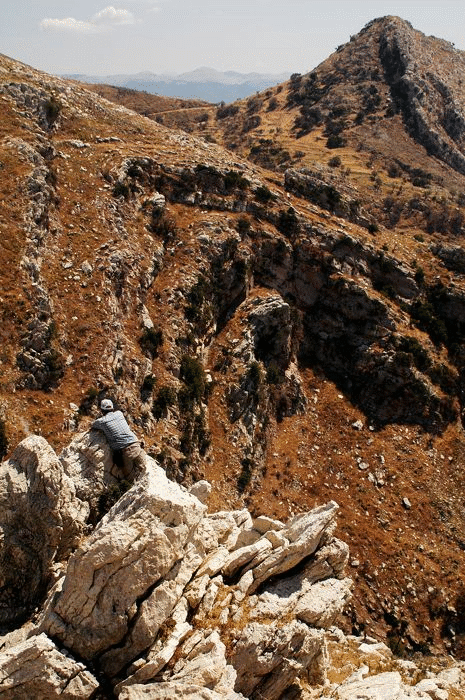
B. Photograph of Three Gorges anticline (middle ground). On the far right (upper right corner) is a resistant rib of limestone which represents the overturned eastern limb of the Cretea syncline. The rock spire that is held up by this limestone rib is known as Agios Georgios, for a chapel of that name is located at its very top. In left foreground, Phil Nickerson looks down into the Three Gorges drainage.
The Three Gorges anticline tends to be overturned westward (see Figures 21 and 29), though northward it becomes more upright (Figure 29B). To the east of it is the St. George syncline, which is overturned westward. The east limb of this syncline is also the west limb of the overturned Cretea syncline. The east limb of this syncline forms the steep rib of limestone that supports the hill-spire on top of which is located a chapel of St. George (“Agios Georgios”) (see Figure 29B), which is located near the hinge of the overturned St. George anticline. One particular profile view of the Cretea syncline is especially dazzling (Figure 30), displaying a nearly isoclinal form expressed by limestones of the Thin Platy Limestone Beds and Thick White Limestone Beds formations. The room problem created during tight synclinal folding apparently created an out-of-the-syncline flow, accommodated by flexural-slip displacements and bedding-parallel faulting. Evidence for this is expressed in a particularly noteworthy profile view of the Three Gorges anticline (Figure 31). The lower part of this fold profile is a perfect upright, symmetrical anticline. In contrast, the upper part of this fold profile displays pronounced (westward) overturned to recumbent folding (see Figure 31). The overall effect is one of disharmonic folding. A likely explanation for the pronounced overturning and disharmony is out-of-the-syncline flow, emanating from the Cretea syncline. To the east of the Cretea is the St. George anticline, which is profoundly overturned westward (Figure 32).
Figure 30. Exquisite landscape expresion of Cretea syncline.

South-directed photograph of nearly isoclinal fold expression of the Cretea syncline. The limestone bedrock includes both Thin Platy Limestone Beds and Thick White Limestone Beds.
Figure 31. Disharmonic folding within Three Gorges anticline.
Nearly normal-profile expression of the Three Gorges anticline. View is northward. This is a beautiful example of disharmonic folding within Thick White Limestone Beds. The lower part of the fold is upright; the upper part of the fold is profoundly overturned westward.
Figure 32. Overturned limb of St. George anticline.
North-directed photo showing overturned nature of St. George anticline. Rocks belong primarily to Thick White Limestone Beds.
VII-C2. Orientation Analysis
As mentioned above, there is a prominent exposure of the Lykaion thrust fault in the eastern part of the study area (see Figures 21, 26, and 28). It strikes essentially N-S, and dips gently (~20° - 30°) to the east. The dip inclination is steeper than that part of the thrust that defines the base of the St. Elijah klippe on Agios Elios.
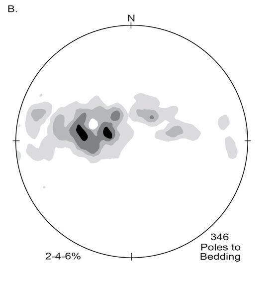
Bedding orientations in the Pan thrust sheet in the eastern third of the area are presented stereographically in Figure 33A. The poles to bedding define a great circle distribution reflecting systematic folding of the strata in the east domain. Fold hinges trend 352° and, on average, are absolutely horizontal. This span of orientation data in the eastern domain conforms nicely to that of all bedding orientation data collected throughout the Pan thrust sheet (Figure 33B): namely a great circle distribution conforming to an average fold-axis orientation of 10°S 5°W.
Figure 33. Stereographic projections in Pan thrust sheet.
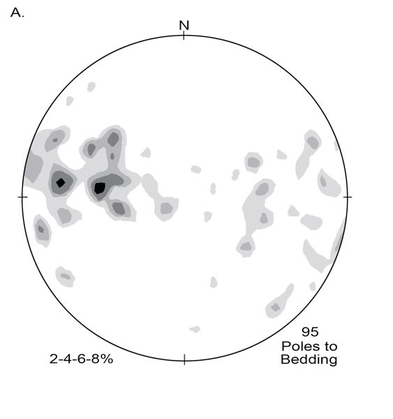
Contours are percentage of total data points falling within each 1% area of the net.
A. 95 poles to bedding in the eastern domain of the Pan thrust sheet.

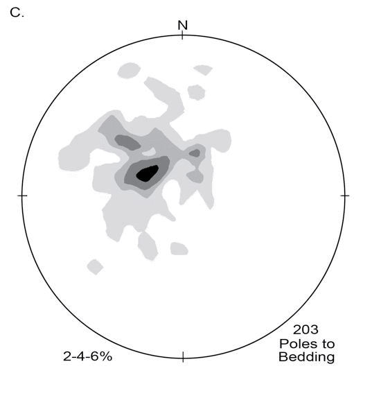
C. 203 poles to bedding throughout the Zeus thrust sheet. See text for explanation.
Map relationships and bedding data reveal that westward overturning is most pronounced in the three easternmost folds, i.e., the uppermost part of the Three Gorges anticline, the Cretea syncline, and the St. George anticline (see Figure 21). The westernmost two folds (i.e., the St. Nicholas syncline and the Upper Walnut anticline) are asymmetrical westward to upright, and for the most part NOT overturned. In fact the Upper Walnut anticline and Sheep Herder’s syncline, which are the most upright, gentle, and ill-defined of the fold structures, together create part of the structural transition between the folded nature of strata in the east domain and the more homoclinal nature of strata in the west domain (see Figure 21). Additional geological mapping is required to pin down the traces and exact geometries of these folds within the northern part of the map area.
The great-circle distributions of bedding data for the Pan thrust sheet (see Figures 33A, B) contrasts sharply with the basic homoclinal attitude of bedding, overall, in the Zeus thrust sheet (Figure 33C). Average orientation of bedding within the Zeus thrust sheet is N35°E, 20° SE.
In the east domain of the Pan thrust sheet, the axial surfaces of the major folds (Sheep Herder’s syncline, Upper Walnut anticline, St. Nicholas syncline, Three Gorges anticline, Cretea syncline, and St. George anticline) steadily strike ~N10°E. However, dips of axial surfaces within this fold system steadily decrease from near-vertical for the Sheep Herder’s syncline and Upper Walnut anticline (on the west) to ~50°E for the St. George anticline (on the east).
VII-D. Active Faulting
VII-D1. Scree Bands as Guides to Faulting
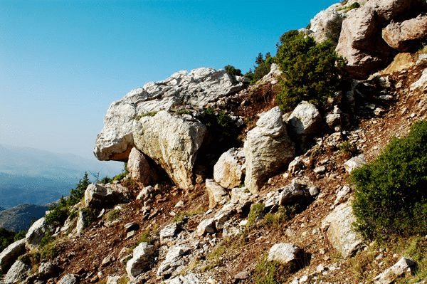
My discovery of active normal faulting in part grew out of puzzlement over peculiar screen bands (composed of limestone blocks) in the area of the upper sanctuary, a good example of which is shown in Figure 34. There are a number of places where these linear swaths and bands of scree occur. They are up to ~12 m in breadth and ~50 m in uninterrupted trace length. Individual limestone blocks show faces that are typically square or rectangular, and the blocks most commonly range in size from fist to bread box. It is obvious there is a ‘fine fraction’ of rock in some of the bands as well, composed of fragments of mudstone and marl, in the form of small chips.
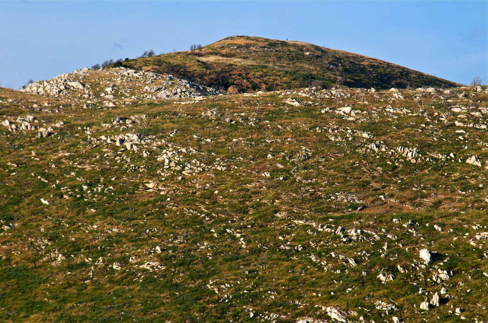
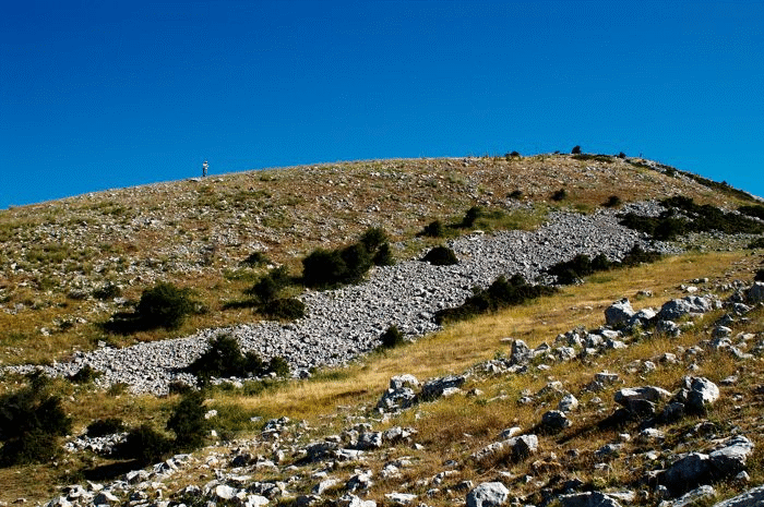
Figure 34. Scree band near base of ash altar summit.
The scree is exclusively limestone blocks from the Thin Platy Limestone Beds formation. Phil Nickerson is negotiating the pile. The scree band marks the trace of an active normal fault.
Scree or talus normally accumulates at the base of a cliff of broken but resistant rock representing the accumulation of rock falls from the over-steepened face. What makes these scree bands peculiar is that there are no cliffs. The scree bands simply occur mid-slope on a hill, or perhaps at or near the base of a hill. In many cases it is apparent that the scree bands coincide with a slight smooth ‘step’ in the topography, on the order of a half meter to several meters (Figure 35). Almost all of the scree bands are derived from Thin Platy Limestone Beds, although there are places where the limestone scree was derived from Thick White Limestone Beds. The progressive development of the scree bands seems straightforward. Episodes of faulting create scarps in the landscape, exposing in places footwall bedrock of Thin Platy Limestone Beds. The fault scarps that develop are initially very steep (greater than ~70º). However, because bedding in this limestone is platy and excessively fractured (Figure 36), weathering and erosion causes the footwall scarps to collapse. They simply cannot hold up to the constant ‘tug’ of gravity. As a consequence, the scree derived from footwall collapse progressively buries the fault surface, and the fault scarp becomes reduced in height and slope angle.
Figure 35. "Steps" in hillside, caused by active faulting.
When the scree bands are viewed from just the right vantage, they are seen to coincide with ‘steps’ or breaks in topography, in the form of subdued rounded scarps, abrupt changes in elevation, and differences in slope angles above and below. This photograph was taken on the flank of the ash altar hill, i.e., Agios Elios.
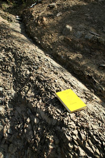
Figure 36. Outcrop expression of weakness of Thin Platy Limestone Beds along fault zones.
The unit breaks up into blocks ~15 cm x 15 cm, reflecting the fact that bedding thickness is essentially the same as fracture spacing. This is a particularly appropriate example of the lack of cohesion of this formation, for this outcrop is immediately adjacent to an active fault zone.
Thus one of the significant discoveries resulting from my geological mapping of the Mt. Lykaion Sanctuary of Zeus was recognition of active normal faulting. The faulting is especially concentrated and/or especially obvious near the crest of Mt. Lykaion in the Zeus thrust sheet, where several formations of the Lykaion klippe are cut and displaced (Figure 37). The mapping of these faults proved to be relatively straightforward, not only because the linear scree bands define the fault trace expressions, but also because beyond the “tips” of the scree swaths it was possible to continue to map active faults on the basis of abrupt truncation and juxtaposition of stratigraphic formations.

VII-D2. Active Faulting within the St. Elijah Klippe
The map pattern of active normal faults in the St. Elijah klippe is presented in Figure 37. I have named these for convenience of reference. From west to east across the summit of the sanctuary they are the Grassline fault, the Temenos fault, the Ash Altar fault, the Chapel fault, the Shepherd fault, and the Ravine fault (see Figure 37).
The Grassline fault is major active normal fault with a trace length of at least 2.5 km (see Figure 37). It strikes NS, dips ~60º-70ºE, and is marked by down-to-the-east offset. Near the summit it passes along a narrow grassy strip (Figure 38), interpreted by David Romano as a possible site of an early stadium in the upper sanctuary. At the north end of the Grassy fault, Thin Platy Limestone Beds on the west (footwall) are faulted against Thick White Limestone Beds on the east (hanging wall) (see Figure 37). Stratigraphic throw is ~65 m. To the south the Grassy fault is marked by ever-increasing stratigraphic throw, up to at least ~150 m (see Figure 21). Because elevation drops along it from north to south, exposures of the Grassy fault southward reveal deeper and deeper structural levels. The Lykaion thrust is clearly cut and displaced by the Grassy fault (see Figure 21).
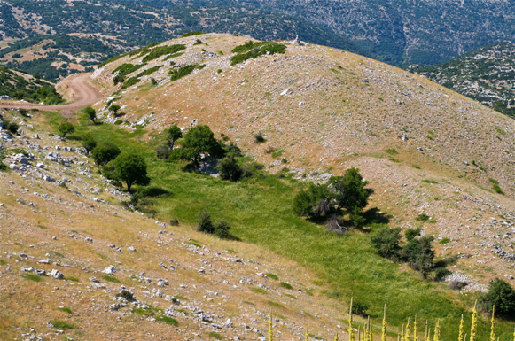
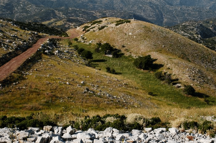
Figure 38. Landscape expressions of Grassline fault.
South-directed view of Grassline fault. Photograph taken from near the top of Agios Elias. The green swath represents an area where alluvium has accumulated, creating a cover of the bedrock. The fault itself is on the western (right) side of the grassy swath, at the base of the ridge. Bedrock underlying this ridge is Thin Platy Limestone Beds. Bedrock exposed on the east side of the grassy swath is Thick White Limestone Beds. Near the intersection of the fault trace and the road the location of the Grassline fault is tightly constrained, for Thick White Limestone Beds (white outcrops) are in direct contact with Thin Platy Limestone Beds.
The Temenos fault is an active normal fault with a trace length of ~700 m (see Figure 37). It strikes N40ºE, dips ~60ºSE. The western part of the fault trace is marked by a broad, thick accumulation of limestone scree (Figure 39A). It can be followed eastward right along the southern flank of the ash altar summit, and just west of the northern boundary of the temenos (Figure 39B). The SE block (hanging wall) of this fault has dropped relative to the NW (footwall block), as evidenced by the various juxtapositions of stratigraphic formations along the fault trace (see Figure 37). Both on the western and northern flanks of the St. Elijah klippe, this fault separates Thin Platy Limestone Beds of the hanging wall from First Flysch Beds of the footwall. Across the summit of the klippe, Thick White Limestone Beds (hanging wall) are dropped down relative to Thin Platy Limestone Beds (footwall). Stratigraphic throw is ~75 m. If this fault cuts and displaces the Lykaion thrust, as we expect it does, the offset is so small that it is unrecognizable; the fault may tip out before reaching the trace of the Lykaion thrust.
Figure 39. Landscape expression of Temenos fault
A. North-directed photograph of the scree band marking the trace of the Temenos fault. The ash altar of the Sanctuary of Zeus is at the very summit at the top of the mountain, right background.
B. Northeast-directed photograph of the continuation of the Temenos fault. Ash altar hill in background. Scree band running parallel to the flank of the hill is the Temenos fault. The actual temenos is the flat area in the middle ground, now being used at times as a parking area. The scree band running from the top of the ash altar hill and at nearly right angles to the Temenos fault is the Altar fault, another active normal fault.
The Altar fault is a northwest-striking, southwest-dipping active normal fault which passes ~10 m west of the ash altar (see Figure 37). Its trace length is only ~30 m, and its displacement appears to be no more than 10 m. The Altar fault appears to cut and displace the Temenos fault, producing a right-lateral separation (see Figure 39B). The presence of an active normal fault so close to the ash altar heightens the sense of the ‘powerful’ nature of the sanctuary. In the summer of 2009 I initiated paleoseismic trenching into a colluvial wedge of limestone-block scree along the trace of the Altar fault. Slickenlined blocks were found to be abundant, creating in my mind the expectation that the fault surface itself will be penetrated during the 2010 field season of trenching.
The Chapel fault strikes N10ºE, is inferred to dip easterly, and has a short trace length of less than 0.5 km (see Figure 37). Near the summit of the upper sanctuary, the Chapel fault separates Thick White Limestone Beds on the east (hanging wall) from Thin White Platy Limestone Beds on the west (footwall). Stratigraphic throw is ~25m. Its trace can be followed north of the Temenos fault. No offset of the Lykaion thrust by the Chapel fault is discernable.
The Shepherd fault (see Figure 37) is a conspicuous normal fault associated in places with a profound linear accumulation of scree (Figure 40). The Shepherd fault strikes N75ºE, dips steeply to the southeast, and has a trace length of ~1.0 km. The hanging wall of this fault throughout most of its trace is composed of Thick White Limestone Beds. Footwall rock, from west to east along the fault trace, progresses down-structure through the Zeus thrust sheet, crossing Thick White Limestone Beds, Thin Platy Limestone Beds, First Flysch Beds, and Chert Series Beds to the Lykaion thrust fault, which it cuts and displaces. From there it cuts downward into the Pan thrust sheet, offsetting Flysch Transition Beds by as much as ~50m. The Shepherd fault is so named because of fault damage to a shepherd’s hut and the burial of a shepherd’s wall and/or hut by the scree.
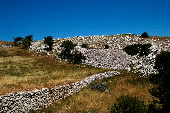
Figure 40. Disturbance of Shepherd's wall by active faulting.

North-northwest-directed view of the Shepherd fault. The Shepherd fault runs along the base of a ridge of Thick White Limestone Beds. The volume of limestone scree is immense. Note that the Shepherd’s wall runs directly toward the band of scree and appears to disappear. In the right background a part of a built structure is evident within, and covered by, the scree.
The Ravine fault branches eastward from near the midpoint of the Shepherd’s fault (see Figure 37). It strikes west-northwest and dips southwest. It conspicuously cut and displaces the Lykaion thrust fault, producing a right-lateral separation of ~225 m (see Figures 21 and 37). Figure 41 is a west-northwest directed view of the Ravine fault at a location where hanging-wall First Flysch Beds of the Zeus thrust sheet are juxtaposed against Flysch Transition Beds and Thick White Limestone Beds in the footwall (which is the Pan thrust sheet). Stratigraphic throw is as great as ~500 m.
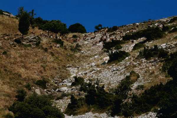
Figure 41. Ravine fault puts First Flysch Beds against Flysch Transition Beds.
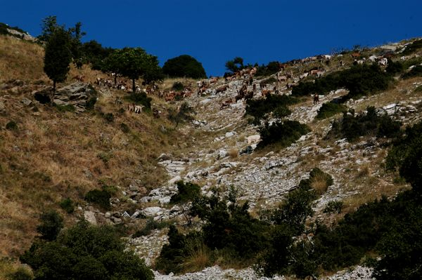
West-northwest-directed photograph of the Ravine fault. The trace of the fault separates grassy ground on the left (south) from white limestone outcrops on the right (north). The fault dips left (i.e. southwest) at a moderately steep angle (~60º). The limestone outcrops are Flysch Transition Beds of the Pan thrust sheet, and represent the footwall of the active normal fault. Note that the grassy ground contains outcrops of brown sandstone, which is First Flysch Beds of the Zeus thrust sheet, representing the hanging wall of the fault. Goat herd for scale.
VII-D3. Active Faulting Bordering St. Elijah Klippe on East
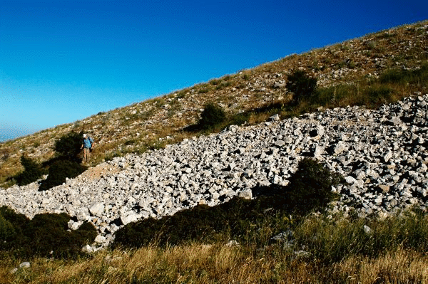
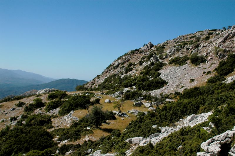
The largest of the active normal faults shape the upper reaches of the eastern margin of Mt. Lykaion, where there are at least two majors north-south-striking, east-dipping normal faults (see Figures 21 and 37). The zone, which I call the Lykeo fault zone has a trace length of at least 1.0 km. The faulting is expressed clearly in a systematic eastward down stepping of the Mt. Lykaion mountain-top surface (Figure 42A). There are at least two subhorizontal structural terraces (featuring both bedrock and scree), which have stepped downward by the faulting. These terraces contain large limestone blocks that have been shaken down from above but managed not to roll off the terrace(s) to the east (Figure 42B).
Figure 42. Landscape expression of the Lykios (active) fault zone.

A. South-directed photograph of the steep eastern flank of the upper reaches of the Sanctuary of Mt. Lykaion. Bedrock is entirely Thick White Limestone Beds of the Zeus thrust sheet. The abundance of scree, and the number of precariously balanced limestone blocks, testify to the active nature of this faulting. The active faults appear to be dipping ~60ºE, given the inclination of the scarp whose profile is so evident. At the base of the uppermost fault/scree slope there is a broad, flat structural terrace. This appears to be the first step down from the eastern edge of the summit plateau of Mt. Lykaion, and reveals a net fault displacement for this part of the zone of at least ~40m.
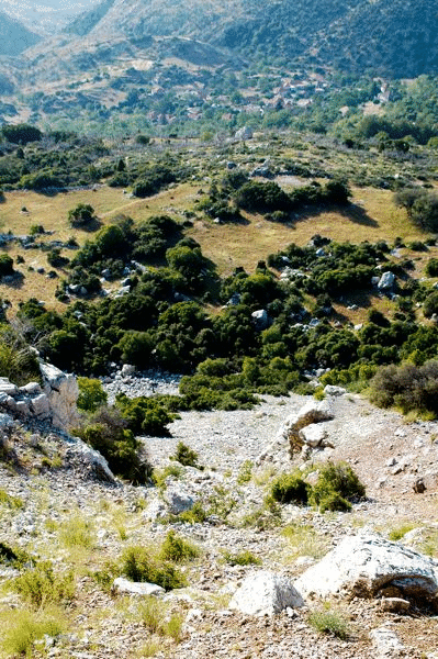
B. Southeast-directed photograph from the eastern edge of the structural terrace noted above. From this vantage a second structural terrace can be seen, which is largely tree-covered. It is represents the tsecond step created by displacements within the Precipice fault system. The village of Ano Karyes is directly downslope, and as noted earlier in the text the village has been built on landslide deposits.
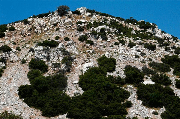
The escarpments along the Lykeo fault zone are tall, at least 40m. Though the underlying bedrock (Thick White Limestone Beds) is covered largely by limestone scree on the terraces and the lower reaches of the escarpments (Figure 43A), there is well-exposed bedrock in the upper portions of the headwalls. Notwithstanding, major bedrock outcrops appear from place to place to have shifted out of original positions and orientations, and some are precariously balanced (Figure 43B). The bedrock occupying the escarpments is unstable, because of steepness and strong internal fracturing. Evidence of rock falls is conspicuous.
Figure 43. Scree deposits and rock falls along Lykios fault zone.
A. Photograph of screen cones descending downward from a combination of limestone bedrock and cohesive landslide deposits of limestone.
B. Large precariously balanced blocks of limestone are perched upon these oversteepened slopes.
The characteristics of this major active normal-fault zone conform nicely to descriptions of active faulting in Greece where limestone is the dominant country rock (Stewart and Hancock, 1988; Goldworthy, Jackson, and Haines, 1992; and Goldworthy and Jackson, 2000, 2001).