Outcrop, hand-sample and microstructure observations
Country rocks
Chotanagpur Granite gneiss is usually strongly foliated; foliation is defined by compositional banding with alternate quartz-feldspar rich- and biotite-hornblende-rich, mm- to cm-scale bands. The rock is coarse grained (1mm and more in grain size), leucocractic and consists of quartz, feldspar, and mafic minerals. It is fractured and fracture planes are commonly healed by silica and iron oxide.
Quartz and plagioclase feldspar constitute ~90% of the granite gneiss. Microcline is present in small amounts. Mafic minerals, such as amphibole and biotite and opaque minerals together constitute ~10% of the rock. Most of the quartz grains show weak to strong undulose extinction with some showing occasional deformation lamellae. Some grains show subgrain rotation recrystallization (Twiss and Moores, 1992). Plagioclase grains are commonly altered to different degrees and appear cloudy in plane polarized light. Amphibolite enclaves occur in isolated outcrops within the granite gneiss. They are massive, hard and consist of hornblende (>60%) and plagioclase with subordinate clinopyroxene and quartz (~15%).
Massive to well-bedded, coarse-grained, clast supported Dubrajpur Sandstone consists of quartz (>95%) as dominant framework grains with fairly uniform grain size. Strong undulose extinction and subgrain in some quartz clasts suggest deformed provenance. Thin bands of conglomerate are locally present within sandstone. Fracture and joint planes are quite common in all types of rocks including fault rocks.
Fault rocks
Outcrop and hand samples
Fault rocks occur along three linear ridges (Fig. 2) represented by cataclasite and gouge (Sibson, 1977). Fractures are common; they are straight to curved and usually healed up by opaque substance that gives rise to distinct deep brown to black colour in outcrops (Fig. 3). The fractures are neither uniformly distributed, nor uniformly oriented, at least on the scale of the exposure; the cataclastic rocks almost always give the impression of having an isotropic cataclastic fabric (Fig. 3). The rock is composed of light-coloured sub-angular to rounded fragments of granitic and sandstone protolith embedded within the fine grained, dark- to light-brown coloured matrix (Fig. 3). The transition of cataclastic rock to the host rock is sharp or progressive where the cataclastic rock band is bordered on both sides by coarser cataclastic rocks in fault related deformation zone.
Figure 3. Massive cataclastic rock in outcrop
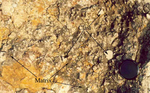
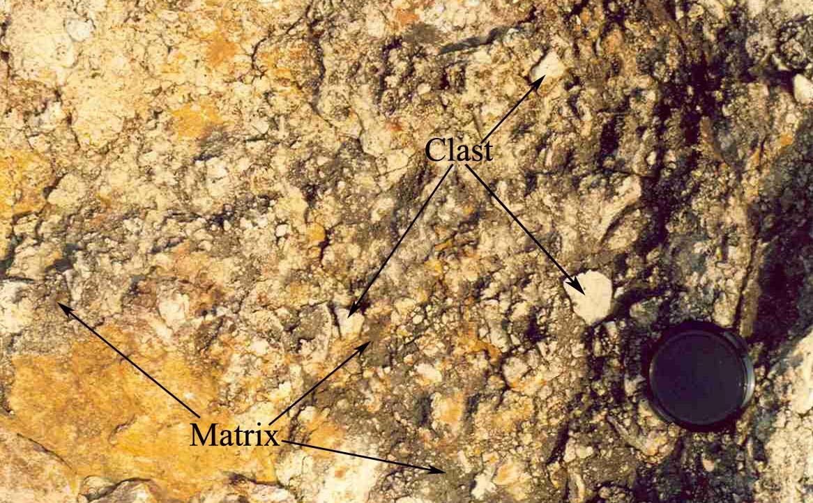
Field photograph showing massive cataclastic rock with clasts of different shape and size (light colour) embedded in a fine grained iron oxide-rich darker matrix.
Figure 4. Microbreccia with clast-in-matrix texture

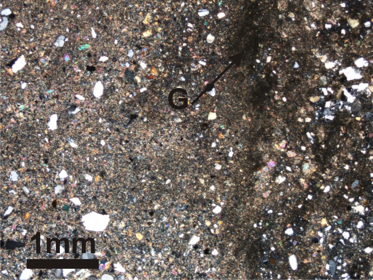
Photomicrograph of microbreccia showing angular to subrounded clasts of single crystals and rock fragments surrounded by matrix of extremely fine rock flour. G, Gouge. Crossed polars.
The fault rocks are indurated, cohesive, massive, hard, compact, and non-foliated (Fig. 3) cataclasites and ultracataclasites in the fault zone. They have low specific gravity and are commonly ochre-yellow to dark brown on weathered surface due to stain of iron oxide solution and off white to light brown on fresh exposures (Fig. 3).
Microstructures
At grain-scale, the diagnostic character of the fault rocks is the clast-in-matrix texture and the clasts or survivor grains are surrounded by a matrix of finer comminuted grains and secondary minerals. Clasts are derived from the host granodiorite gneiss, but occasional clasts from Dubrajpur sandstone are seen. The clast-in-matrix texture can be further subdivided into cataclastic and granular textures (cf. Twiss and Moores, 1992). The microstructures were studied using polarized optical microscopy and cathodoluminescence microscopy. These techniques were useful in separating several generations of microfracturing based on their morphology and cross-cutting relationships. Details of cataclastic rocks can only be seen under microscope.
Angular blocks of material with more finely comminuted material, produces an originally cohesionless mass known as fault breccia or microbreccia where the largest fragments are up to about 5cm. in length in the fault rocks. When the comminuted material is granulated to fine flour of rocks (0.1 to 100μm in size) the product is known as gouge (Sibson, 1977; Scholz, 1990). Both breccia and gouge are cohesionless material but they become impregnated and sealed by crystal growth of silica in the voids to produce cemented breccia or cemented gouge (Stel, 1981). In the present work, classification of Sibson (1977) and Scholz (1990) has been followed to name the fault rocks.
The fault rock dominantly (more than 90%) consists of large and medium size clasts of quartz, feldspars and rock fragments (length varies from 0.02mm to 2.8mm and width from 0.01mm to 1.80mm but the majority of the clasts are 1 mm or less). Largest clasts are usually of rock fragments. The clasts are embedded in a fine grained groundmass that consists of smaller grains varying in size from less than 0.01 mm to 0.85 mm (Fig. 4). Locally gouge is present as irregular bands and patches (Fig. 4). Opaque clasts are commonly present as isolated grains; patchy aggregates of fine grained opaques are also present within the groundmass and along the boundary of the large clasts.
There is a fair amount of heterogeneity in the size of the clasts and it varies widely from one exposure to another and this can be observed even in micro-scale. Most of the clasts are highly angular, squarish to sub-squarish, elliptical or triangular or rectangular in shape and commonly show strong undulose extinction and incipient recrystallization. Groundmass dominantly consists of very fine grained to submicroscopic cataclastic material with secondary silica that appears as dark aphanitic mass under optical microscope. Fine grained flour material of cataclastic rocks (gouge) is mostly aphanitic and commonly occurs as narrow discontinuous bands transecting across early cataclastic rocks (Fig. 5) and also along fractures in large clasts. Width of these gouge zones varies from less than 0.02mm to 2.2mm. Isolated relatively large clasts are occasionally present in gouge. On the basis of the percentage of matrix majority of the cataclastic rock belongs to cataclasite (matrix 50-90%), although it varies from protocataclasite (10-50% matrix) to ultracataclasite (<90% matrix) (Sibson, 1977; Scholz, 1990). Thin pressure solution seams are present in gouge zones. Once the finer material reduces below a certain grain size pressure solution become an important mechanism of deformation. Fractures in cataclastic rocks are often filled up by quartz veins (Fig. 6), and the groundmass of the cataclastic rocks is always silicified. The silicification of cataclastic rock has produced silicified cataclasite. In some cases, the highly fractured masses of fine grained quartz resemble dynamically recrystallized quartz, but deformation is dominated by brittle processes as suggested by Evans (1988). The silica of the groundmass remains dark in plane polarized light and are otherwise unobservable if not seen using cathodoluminescence (Figs. 7a and b).
Figure 5. Late phase gouge on early cataclastic rock
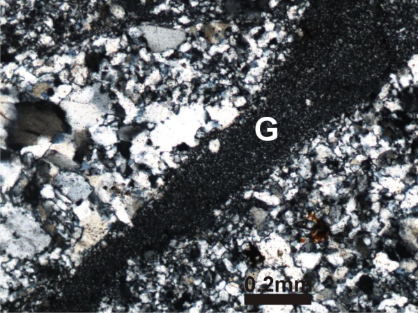
Photomicrograph of microbreccia showing fine-grained to submicroscopic cataclastic rock (gouge, G) formed on coarser-grained cataclastic rock along thin micro zones (G). Crossed polars.
Figure 6. Silicified breccia
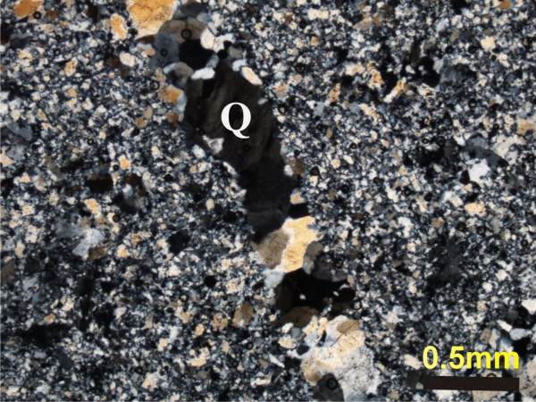
Photomicrograph of silicified breccia showing fracture filled with quartz crystals which show signature of plastic deformation suggesting deformation continued after silicification. Q, quartz crystal. Crossed polars.
Figure 7a. Cathodoluminescence image of silicified cataclastic rock

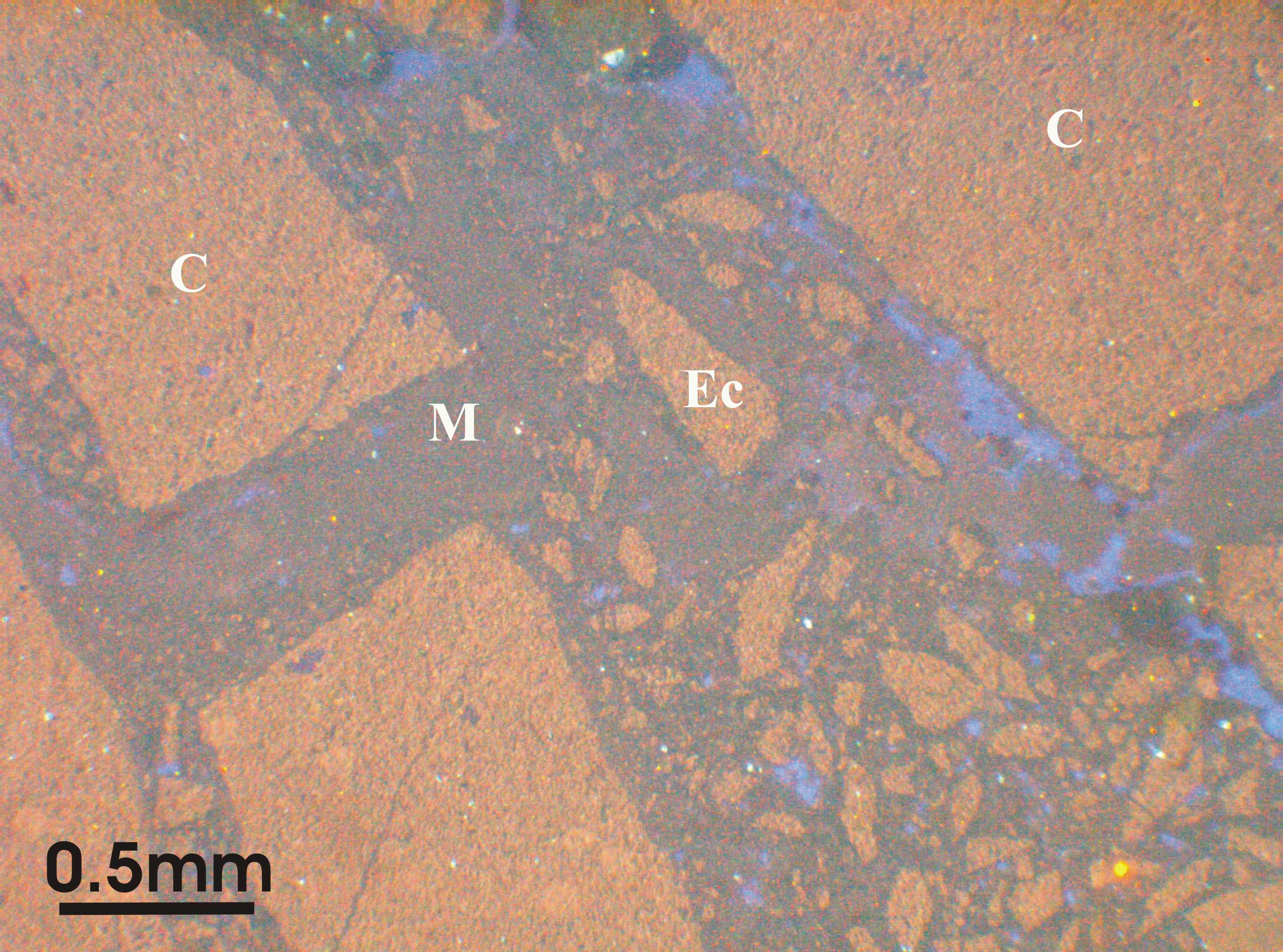
Microfracture zone consists of randomly oriented smaller clasts (Ec) of varying size and shape floating in a silicified (M, dark grey and blue) submicroscopic matrix. Healed intragranular extension fractures occur in large clasts (C). Note the very sharp boundary of the fracture zone with clasts.
Figure 7b. Cathodoluminescence image of silicified cataclastic rock
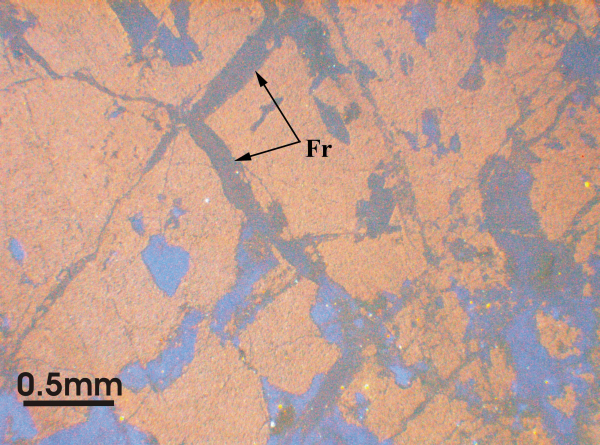
Showing conjugate set of fractures (Fr) healed by silica (dark grey and blue). Note that later generation intragunalar shear cracks displace older silica vein (lower left corner). Crossed polars.
Figure 7c. Photomicrograph of breccia with transgranular fracture
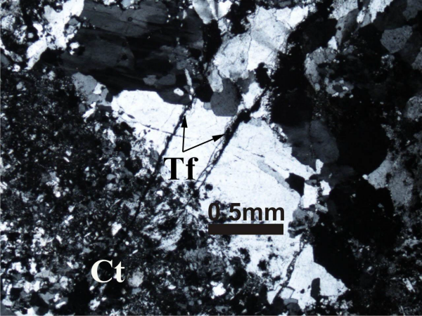
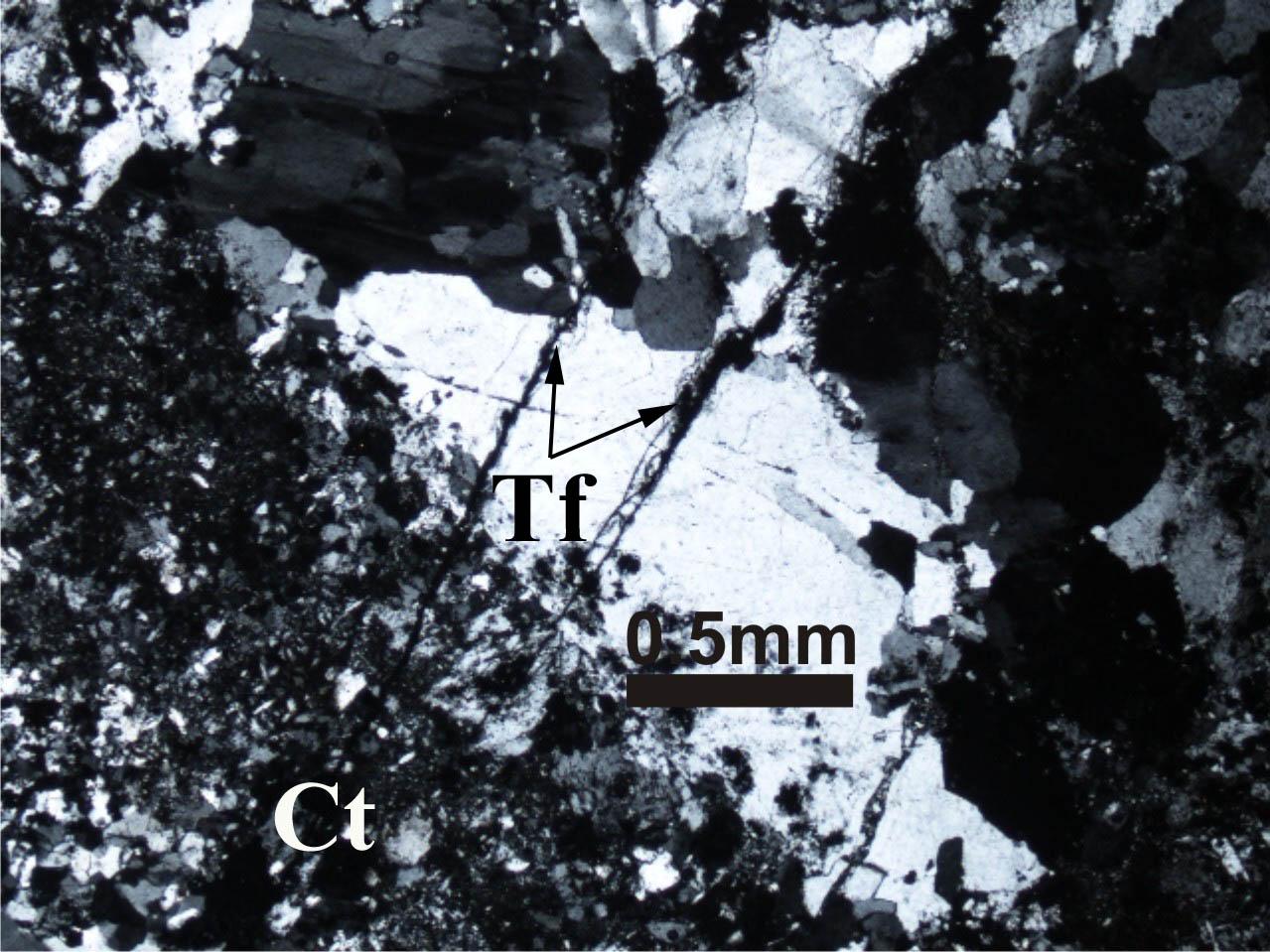
Showing cataclasite zone (Ct) bordered by wall rock affected by transgranular fractures (Tf) lined by thin cataclasite zone cutting across older silicified cataclastic rock layer suggesting multiple phases of cataclasis. Crossed polars.
Figure 7d. Photomicrograph of breccia with transcrystalline shear fracture
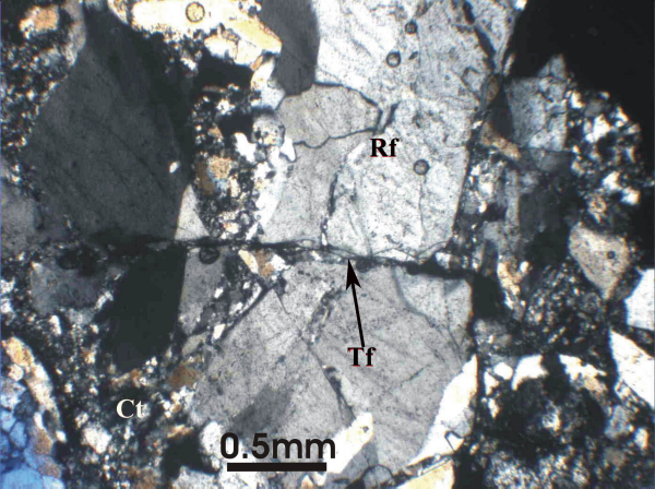
Showing intergranular, continuous transcrystalline shear fracture (Tf) across large clast. Fractures are lined by thin cataclasite zone. Rf, rock fragment; Ct, cataclastic zone. Crossed polars.
The cataclasis is visible as a network of cracks, sometimes straight and sometimes less regular. The microfractures die out within a short distance (intragranular cracks) or continue for a long distance as grain boundary cracks or intergranular cracks. Fractures are ubiquitous within the clasts as well as in groundmass. Fracture density varies from grain to grain. The microcracks may be unhealed fractures but commonly they are healed (Figs. 7a-d). The fractures are branching at places and comminuted subgrains are rotated along fractures (Figs. 7a, d).
A variety of different crack geometries, morphologies and orientations are developed in the fault rocks. The cracks may be broadly divided as intragranular cracks (contained within single grains) and intergranular cracks (Figs. 7c, 7d) (within a length of several grain diameters) (Kranz, 1983; Ismat and Mitra, 2001; Passchier and Trouw, 2005). They are typically blunted at grain boundaries, either because they run into a more ductile matrix or because they impinge on a grain with a suitably oriented glide system that allows the stress concentration to be dissipated (Mitra, 1978). Intragranular cracks formed under dominantly plastic deformation conditions are crystallographically controlled and may not be directly related to regional stresses. Other intragranular cracks that formed during initial fracturing under cataclastic conditions develop only in grains that are optimally oriented to the deforming stress (Ismat and Mitra, 2001). This type of deformation results in grain-size reduction in a thin deformation zone in rocks. Intragranular cracks having the same orientation in many grains suggest that they are brittle and result from far-field stresses that also produced the large transgranular cracks (Ismat and Mitra, 2001). These cracks suggest increasing deformation resulting in coalescence of some cracks to form a single, continuous fracture (Figs. 7c, 7d).
Intergranular cracks range in length from a few grain diameters to continuous fractures in the rock (Figs. 7c, 7d). Transcrystalline fractures (fractures running through several grains) are lined by finer cataclasite associated with more intense deformation (Figs. 7d, 8). They generally form under elastico-frictional deformation conditions under which cracks, once nucleated, can coalesce with other cracks or propagate unstably due to stress concentration at crack tips. These types of cracks have been described as Brittle Intergranular Fracture type 1 (BIF1) (Gandhi and Ashby, 1979; Ashby et al., 1979; Atkinson, 1980) and have been previously described from quartzites (Lloyd and Knipe, 1992). Crack propagation is blocked by higher pressure and is also controlled by material inhomogeneities. If the matrix has lower fracture strength than framework grains cracks tend to nucleate at grain-grain contact or grain-matrix interfaces and propagate along grain boundaries (Ismat and Mitra, 2001). If there is no strength difference between framework and matrix, cracks may nucleate within framework or matrix, and can propagate across grain-boundaries and through successive grains (Fig. 7c); these intergranular cracks are referred to as transgranular cracks (Ismat and Mitra, 2001).
In zones of strong deformation, smaller framework grains show particularly strong undulose extinction while larger grains are fractured. These fractures developed typically at dislocation pile-ups and are oriented at high-angles to glide planes. They are intragranular cracks and lead to reduction of grain size in the rock (Fig. 8). There are healed shear cracks with grain boundaries and twin lamellae offset along them (Fig. 7d).
Figure 8. Silicified cataclasite zone

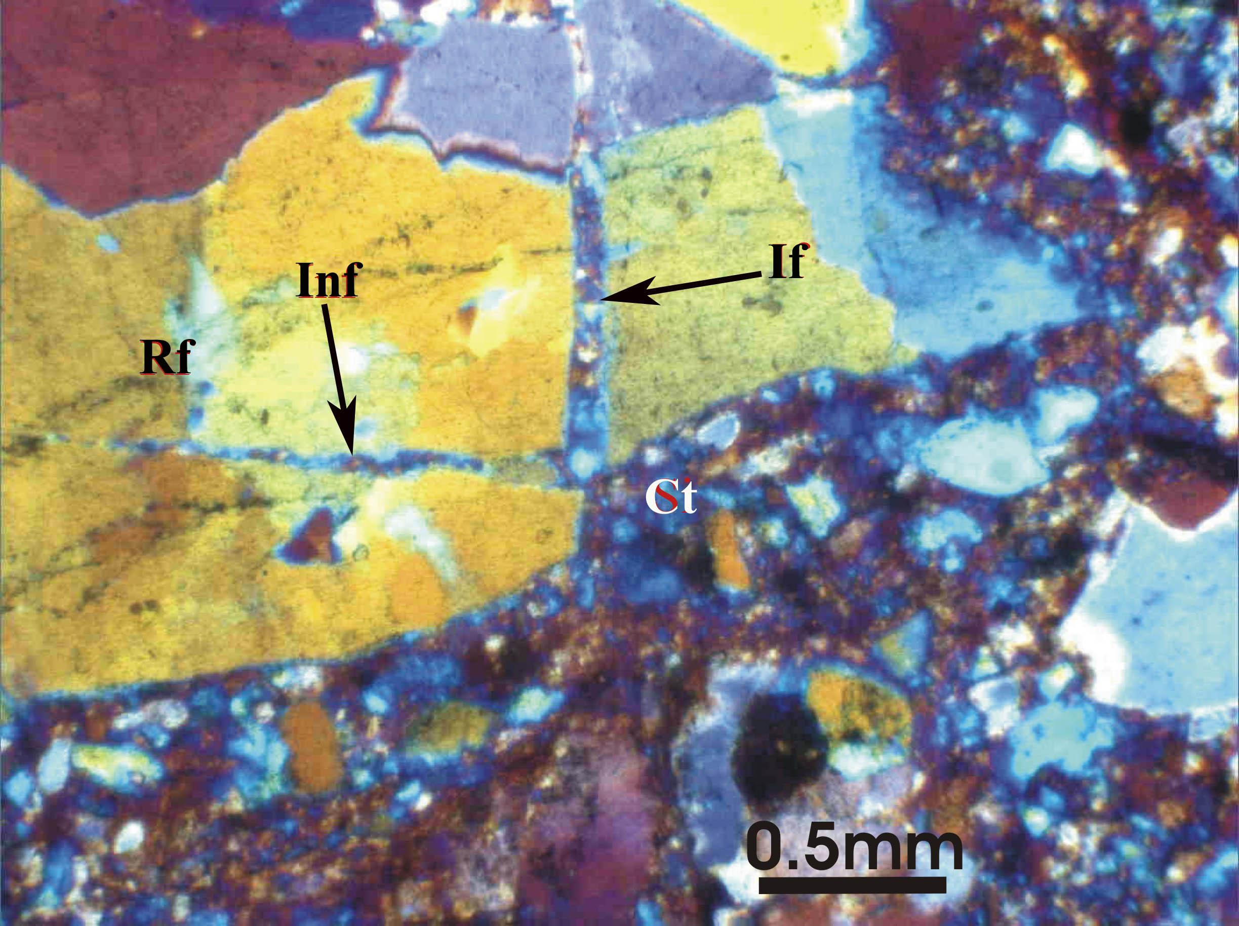
Photomicrograph of breccia with gypsum plate showing intensely fractured silicified cataclasite zone (Ct) and less deformed wall rock (Rf) contains conjugate set of fractures (If and Inf) lined by thin cataclasite zone. Note the sharp angular boundaries of the clasts. Crossed polars.
Wider intergranular zones of fine-grained cataclasite, which completely reformed the original grains, show microstructures resembling sintered material (Anderson et al., 1974). Extremely fine-grained (approximately 1µm) materials of the reformed grains show interlocking grain boundaries in some sections (Fig. 9). Because of their fine grain-size and three dimensional interlocking nature the boundaries often appear a little fuzzy under the microscope (Fig. 9). The development of intergranular and anastomosing cracks, usually parallel to cataclastic zone boundaries, indicate that these zones grew in thickness by fracturing in adjoining rocks to reduce asperities at the wall rock–cataclastic zone boundary (Mitra, 1984). Transgranular cracks that branch from cataclastic zones are observable in thin sections. Later phase cracks crosscut the previous features as well as matrix in wider cataclasite zones.
Figure 9. ‘Penetrative’ transgranular sintered zone
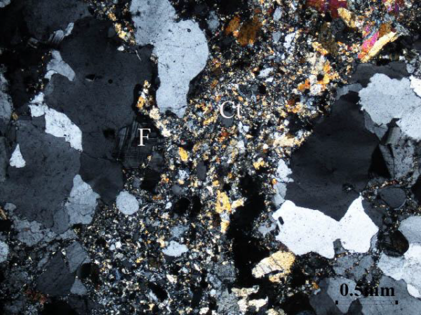
Photomicrograph of breccia showing wider ‘penetrative’ transgranular sintered zone (Ct) of interlocking fine-grained cataclastic zone which completely reformed the original grains. F, feldspar. Crossed polars.
There are also thick (up to 2mm) microzones of cemented cataclasite with angular, randomly oriented fragments that probably grew from thinner zones by incorporating angular fragments from the wall rock into the zones (Fig. 7a). Under elastico-frictional deformation conditions, the finer-grained matrix is stronger than the framework, and microcracks are likely to grow from pre-existing flaws within the framework grains (Fig. 7a) (Cleavage I cracks of Gandhi and Ashby, 1979), and only in those grains that contains flaws that are in suitable orientation to grow under the externally applied stresses (Sussman, 1995).
Length of the fractures varies from 0.23mm to more than 4.5mm and width of the fractures zone within grains (crushed zone within grain due to grain crushing, e.g. Figs 7a and 8) varies from less than 0.04mm to 0.05mm. Conjugate set of fractures in clasts are common (Figs. 7b, 8) with varying width from 0.01mm to 0.09mm. They are mainly intergranular to transgranular. These fractures are continuous, transecting, cutting across cataclastic mass through the clasts (Figs. 7b, 7c) sometimes irregular in their orientation, branching and often coalescing and are healed by silica and iron oxide precipitations (Figs. 7a-c). Fractures vary from straight, wavy, sharp to zigzag in pattern following the cleavage planes of feldspar grains. Under cathodoluminescence, the sealing of fractures by silica is very distinct; and it is observed that almost all the fractures are healed up by silica irrespective of their thickness and nature (Figs. 7a, 7b).
At places the fractures are lined with thin films of gouge consisting of very fine-grained, floury crushed silicified material (Figs. 7a, 7c, 7d). Thin micro gouge zones developed on older cataclasite; thickness of these zones varies from 0.2mm to 3mm (Figs. 5, 10).
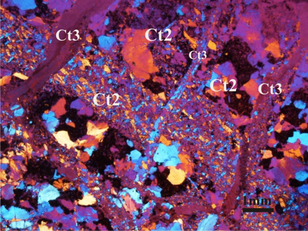
Figure 10. Multiple phases of cataclasis
Photomicrograph of intensely deformed silicified cataclastic rock showing multiple phases of cataclasis. The later cataclastic rock zone (Ct3) with sharp boundaries cutting across older cataclastic rock (Ct2). Please note that in the central part the Ct2 zone is displaced along Ct3. Crossed polars with gypsum plate.
The cataclastic rocks show recataclasis of earlier cataclastic rock. The repeated cataclasis is marked by the following evidences: a) clasts of older cataclastic rock is present within younger cataclasite (Fig. 11), and b) the older cataclasite is further crushed and granulated by fracturing and thin gouge zones running across the older cataclastic mass affecting both the matrix and the clasts (Figs. 5, 10). These gouge zones and films are formed in high strain zones suggesting strain partitioning in microscale. All these features suggest brittle on brittle deformation.
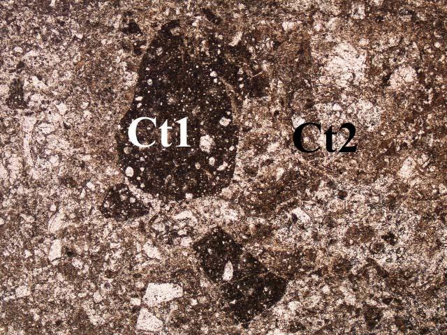
Figure 11. Clasts of older cataclastic rock within later cataclastic rock

Photomicrograph of reactivated cataclastic rock showing clasts of older rounded to subangular clasts of earlier cataclastic rock (Ct1) embedded by later cataclastic rock (Ct2).