Experiments
In order to illustrate how flanking folds develop by the two main mechanisms mentioned we present a series of analogue experiments, using a transparent putty in a simple shear box. Experiments were carried out with either a rigid piece of cardboard or open fractures at various initial positions.
EXPERIMENTAL SETUP - APPARATUS
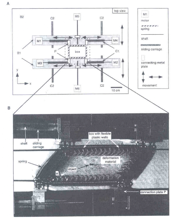
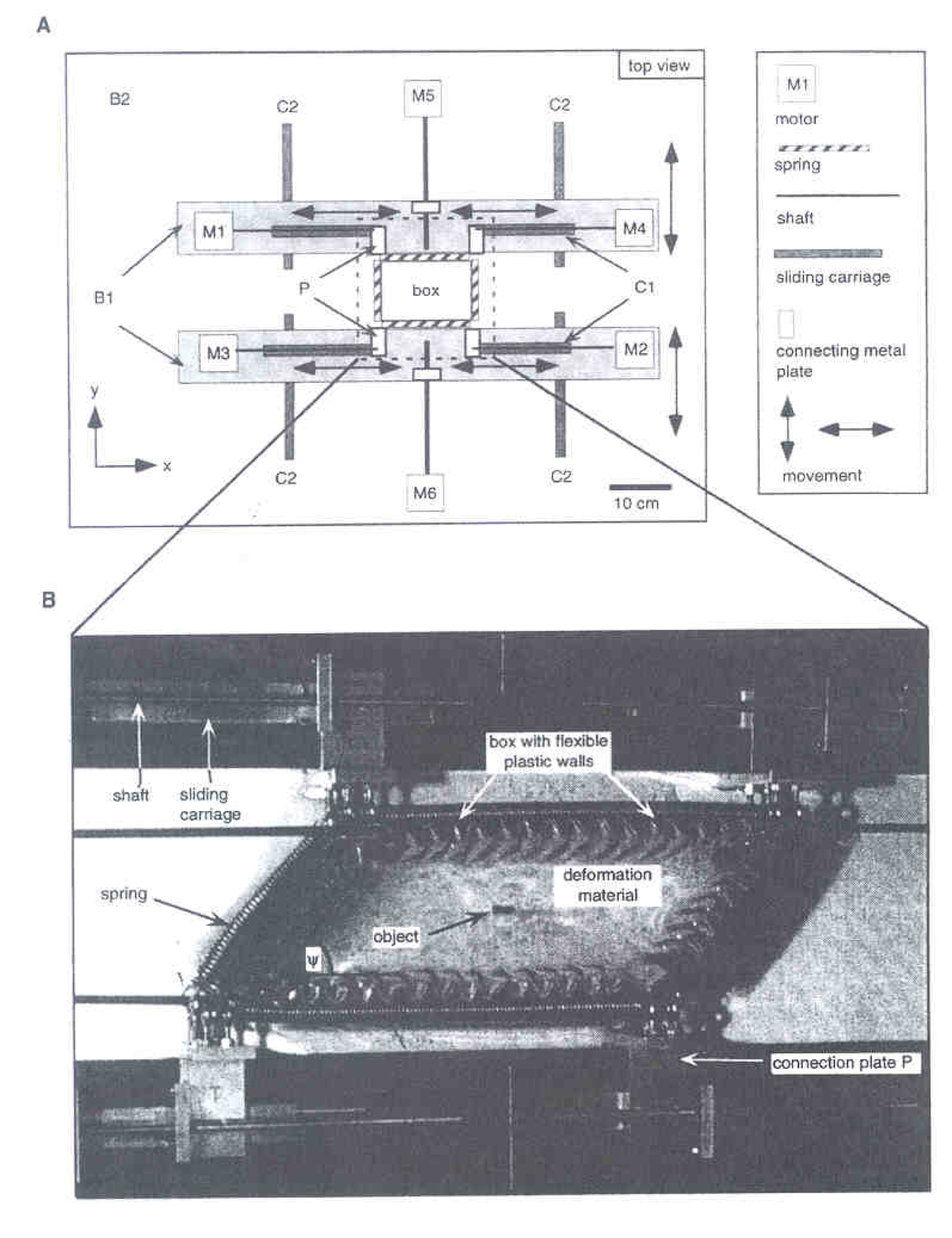
The apparatus used for the analogue experiments consists of the four-sided deformation box (fig. 3) described by Piazolo et al. (2001). Plexiglas segments are connected with flexible plastic to form a wall of chevron-folded pistons (Fig. 3). Metal springs on the outside allow for homogeneous contraction and extension of the walls. The corners of the springs are connected to aluminium plates (P in figure 3). Each plate is attached to a sliding carriage (C1 in figure 3) operated by a motor (M1, M2, M3 and M4) to control the movement in the x-direction. The motors are attached to two PVC boards (B1). Two additional motors (M5) control the movement of the PVC boards along sliding carriages (C2) in the y-direction. The entire assembly is attached to a basal plate (B2). The maximum extension of the walls is approximately 35 cm in the x-direction and 25 cm in the y-direction. Towards the edges of the box, deformation becomes increasingly less homogeneous. The top of the box is open.
The six motors are controlled by the PC-program LabView and allow five different transpression regimes ranging from simple shear to plane strain conditions by defining the kinematic vorticity number and the stain rate along a specific axis. The maximum shear strain that can be reached is around two, depending on the original geometry of the box. During the experiment, pictures of the top of the box are taken by a stationary digital camera. The shear box was lighted from below through the transparent basal plate. Pictures were taken every 300 seconds and later combined to generate Canvas movies.
Materials
The matrix material used in the deformation box is polydimethyl-siloxane (PDMS, trade name SMG 36), a polymer manufactured by Dow Corning, Great Britain. PDMS is a transparent non-toxic polymer with a density of 0.965 g/cm3 and a viscosity (at room temperature) of 5.0*104 Pa s. The material shows Newtonian viscous flow behaviour for strain rates <5*10-1 s-1 (Weijermars, 1986). Glycerin was used at the bottom of the box as a lubricant to reduce basal shear, but this is non-reactive with the PDMS and has a lower viscosity (1.55*10-2 Pa s) and a higher density (1.17 g/cm3).
To represent a rigid CE oblique to HE during deformation, a 1 mm thick and ~4 cm long piece of cardboard was placed in the centre of the box (movie 1). To represent fluid filled fractures or veins that do allow slip during deformation, we used two methods; (1) two pieces of overhead-projector plastic with Silicone gel (200/12.500 CS Fluid, manufactured by Dow Corning, Great Britain) in between, which were allowed to slip past each other (Movie 2, 4). The viscosity of the Silicone gel (1.25*104 Pa s) is about 40 times lower than that of the PDMS; (2) an open fault, created by making a vertical knife cut in the putty which was filled with a drop of lubricating kitchen soap to keep the fault from healing (Movies 3 and 5).
Experimental procedure
The basal plate was lubricated with a thin film of glycerin after which the PDMS was set into the deformation box. We let the PDMS settle for three hours to eliminate most of the trapped air bubbles until the upper surface smoothened. A cut of ~ 4 cm long was made in the centre of the box at angle α, where α is the angle between the CE and the HE. A piece of cardboard, overhead-projector paper with glycerine, or lubricating kitchen soap was placed inside the cut, after which we let the PDMS settle for another hour. A 0.5 x 0.5 cm carbon powder grid was set on the top of the PDMS using a non-fixated plastic sheet photocopy of a regular grid, which was pressed onto the PDMS to transfer the line pattern from the plastic to the putty. Again, we let the PDMS settle for another hour before the experiment was started.
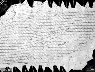
The experiments were conducted under simple shear conditions with initial box dimensions of 210 mm x 180 mm. The displacement applied by motors M1, M2, and M3 was set at 150 mm with a velocity of 0.02 mm/s. Each experiment took 7500 second, resulting in a shear strain of 1.65 and a shear strain rate of 2.2*10-4 s-1. All experiments were carried out at room temperature.
Experiments
The first experiment used a 1 mm thick piece of cardboard at an initial position α = 90°. The second through fifth experiments represent fractures / veins that allow slip during deformation, oriented at initial positions of α = 90°, 135° and 160° respectively.
RESULTS
Animation Movie 1. Flanking folds along a rigid object, α = 90°
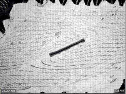
During rotation of the cardboard model-CE, an anticlinal and synclinal hook-type flanking fold train develops in the hanging- and footwall respectively, with axial surfaces parallel to the CE. Most intense folding occurs at the upper tip of the CE in the hanging wall and in the lower tip of the CE in the footwall. The HE shows significant extension parallel to the axial surfaces within both fold hinges. Note that the horizontal markers above and below the CE display synforms and antiforms respectively, formed due to the fact that the CE does not stretch; as a result, the material over and below the CE undergoes extra stretch, resulting in the opposite fold geometry on both sides and a "necking structure" of the HE at the tips of the CE. Progressive deformation results in amplification of the fold trains. The final structure generated is a hook-type flanking fold without slip and with over-roll according to the classification of Coelho et al. (2005). A natural equivalent of this experiment could be a short competent vein within a less competent matrix.
Animation Movie 2. Andersonian flanking folds - rigid fault walls - α = 90°
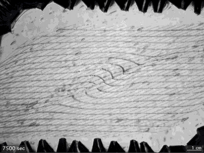
In the early stages of the experiment, increasing antithetic slip is observed along the CE with increasing rotation of the CE. Anticlinal and synclinal fold trains develop in the hanging- and footwall respectively, with axial surfaces parallel to the CE. Most intense folding occurs at the centre of the CE and decreases towards the tips. Only minor extension in the fold hinges is observed. Note the reverse steps in the HE at the tips of the CE, with up-stepping markers the upper tip and down-stepping markers at the lower tip. With progressive deformation, the reverse slip gradually changes into normal slip along the CE at the end of the experiment. The final structure generated in the horizontal marker lines is a hook-type flanking fold with normal slip (negative slip, negative lift and over-roll according to the classification of Coelho et al., 2005). The folds in the horizontal marker lines have their maximum interlayer separation at some distance from the CE because the inserted plastic sheets cannot stretch. Away from the centre of the CE, the fold shape is clearly different on both sides of the CE, resulting in asymmetric, lobate- cuspate pairs, the cusps being located on the CE; tight on one side, more open on the other. A natural equivalent of this experimental result could be alteration rims along an open slipping fracture.
Animation Movie 3. Andersonian flanking folds -deformable fault walls - α = 90°
This experiment is very similar to the previous one, but illustrates what happens if a stretching fault or free-slipping fault exists in a ductilely flowing material (Means 1990; Barr and Housemann 1996). There is a clear transition during the deformation process from reverse to normal slip along the fault. Also, the fold shape is different from the previous experiment; the maximum separation of layers in now directly along the fault plane, not away from it. The hook shape of folds is less pronounced, and there is a more symmetrically distribution of the fold shape on both sides of the CE. A natural equivalent of this experimental result could an open, slipping fracture during ductile flow.
Animation Movie 4. Andersonian flanking folds - rigid fault walls - α = 135°
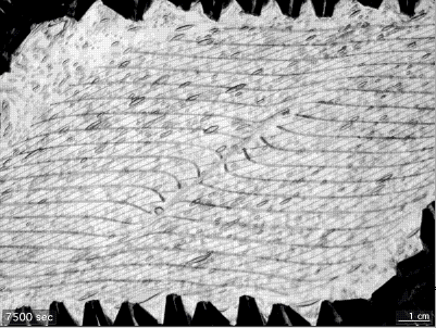
During the entire experiment, reverse slip is observed along the CE with increasing rotation of the CE, although the slip halts and is about to change to normal at the end of the experiment. Anticlinal and synclinal fold trains develops in the hanging- and footwall respectively, with axial surfaces parallel to the CE. Most intense folding occurs at the center of the CE and decreases towards the tips. Only minor extension in the fold hinges is observed. Reverse steps in the HE occur at the tips of the CE, with up-stepping markers at the upper tip and down-stepping markers at the lower tip. Initially, the flanking folds in the horizontal marker lines are shear band type, but after the CE rotates through an angle of α = 90°, they change to hook-type. The final structure generated in the horizontal marker lines are hook type flanking folds with reverse slip (negative lift and over-roll according to the classification of Coelho et al., 2005). Away from the centre of the CE, the fold shape is clearly different on both sides of the CE, resulting in asymmetric, lobate-cuspate pairs, the cusps being located on the CE; tight on one side, more open on the other. A natural equivalent of this experimental result could be alteration rims along an open slipping fracture.
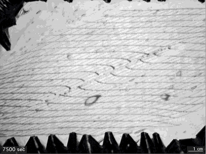
Animation Movie 5. Andersonian shear bands -deformable fault walls - α = 160°
This experiment shows an open fault, filled with lubricating kitchen soap, at a small angle to the horizontal marker lines. In this orientation, a fault is strongly shortened but rotates little during progressive deformation; as a result, shear band type flanking folds develop. In addition, the horizontal marker lines bends towards the CE on both sides, creating an opposite antiform-synform pair. This is due to the enhanced shearing rate along the lubricated fault with respect to the far field flow.
Figure 3. Deformation apparatus
A. Schematic drawing of deformation apparatus (view from the top) where x and y are along symmetric axes of apparatus. B1 are PVC boards, B2 is the base plate, C1 is the set of 4 sliding carriages parallel to x-direction, C2 is a set of 4 sliding carriages parallel to the y-direction, P are connecting aluminium plates, and M1-M6 are motors. B. Close up of deformation box with flexible walls (view from top). Angle ψ is the angle between the sides of deformation box. (Piazolo et al., 2001).