Finite offset of marker lines
We modelled the slip surface as a rigid elliptical object with a high aspect ratio (50) embedded in a zero Reynolds number linear Stokes flow. The Newtonian material is decoupled from the object, which allows slip between the matrix and the inclusion. Similar to fractures modelled as weak inclusion with high aspect ratios (Kocher and Mancktelow, 2005), the slip surface in our model has no stable position except parallel to the fabric attractor and the rotation rate is almost identical to a passive marker (Exner et al., 2004). Although slip along the inclusion induces a perturbation flow field in its vicinity, the flow field does not influence the rotational behavior of the object itself.
The model is based on Jeffery’s (1922) well-known solution for a rigid ellipsoid in free-space Stokes flow where the interfacial velocities equate. An applied velocity field is greatly perturbed close to the ellipsoid but this perturbation vanishes at great distances from the ellipsoid. To adapt this model to account for slip at the interface, normal velocities at the boundary are equated and a free-slip boundary condition is applied by setting tangential surface tractions to zero. The latter can be achieved by setting internal tractions to zero and equating these with the external tractions yielding a solution for the ellipsoid velocity gradient tensor (see Appendix A in O’Connor, 2008). For a complete derivation of this model in two-dimensions see Mulchrone (2007).
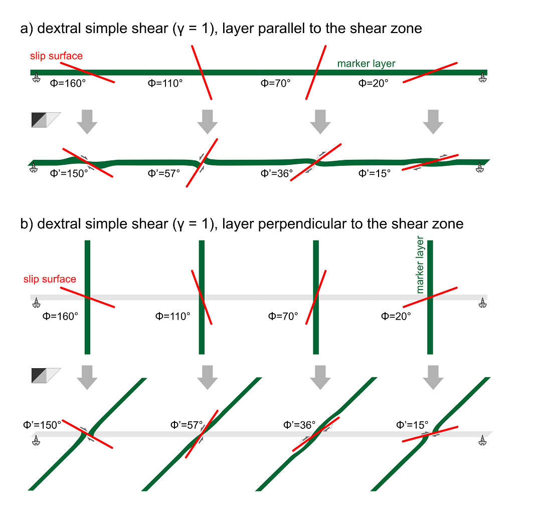
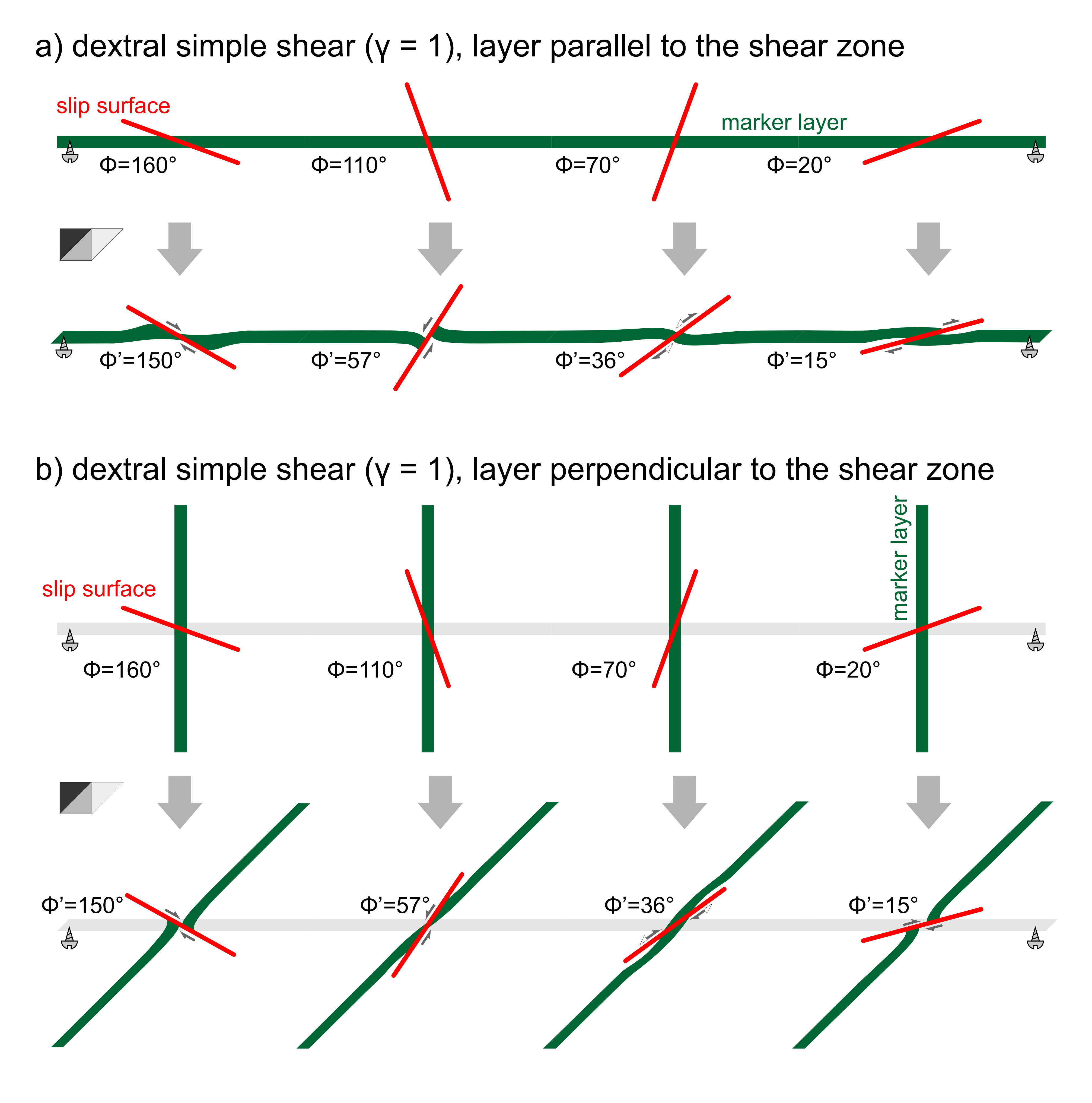
Figure 4a shows the deformation of a passive marker layer, which is deformed by dextral simple shear with a shear strain of γ = 1. Similar to previous physical and numerical models (e.g. Grasemann and Stüwe, 2001; Grasemann et al., 2003; Exner et al., 2004; Kocher and Mancktelow, 2005; 2006), the marker layer is parallel to the shear zone boundary (i.e. the fabric attractor). Slip surfaces are oriented with an angle of Φ = 160°, 110°, 70° and 20° with respect to the shear direction (measured anticlockwise). During simple shear deformation the slip surfaces rotate to orientations of Φ’ = 150°, 57°, 36° and 15°. For detailed discussion of the resulting structures including general shear boundary conditions, Non-Newtonian and anisotropic materials, the reader is referred to the modelling studies cited above. Note that in both Cartesian reference frames (x-axis either parallel to the shear zone boundary or parallel to the slip surface) the structures developed along the slip surfaces with Φ’ = 150°, 57° would record a “missing section” and would be classified by most structural geologists as extensional. On the contrary the slip surfaces with Φ’ = 15° would be recognized as a “thrust” recording a “contractional” offset of the marker layer. The structure with Φ’ = 15° records essentially no offset (or more accurately, a small thrusting component) because it initiated with antithetic slip but during progressive rotation of the slip surface, it crosses the principal stress direction σ3 where the shear sense is reversed to synthetic. However, it is important to emphasize that the modelled deformation is simple shear and since the green marker layer is parallel to the shear zone boundary, its total elongation is zero. The local thickness change and offset of the marker layers in the vicinity of the slip surface is only controlled by the heterogeneous perturbation deformation, which diminishes at some distance to the fault.
Figure 4. Finite deformation (dextral simple shear, γ = 1) of a marker layer
Finite deformation (dextral simple shear, γ = 1) of a marker layer along a slip surface with different initial orientations. a) layer parallel to the shear zone. b) layer perpendicular to the shear zone.
The model in Figure 4b has exactly the same boundary and initial conditions except that the green marker layers are oriented perpendicular to the shear zone boundary. This has a major influence on how the structure develops during progressive shearing, because the layer does not remain parallel to the fabric attractor but rotates together with the slip surface (but at a different rate) into the shear direction. While the slip surface with Φ’ = 150° has a clear extensional offset, the description of the slip of other structures is more complex and partly dependent on the chosen reference frame. In the frequently used Cartesian reference frame, where the x-axis is parallel to the shear zone boundary, the slip surface with an initial angle of Φ = 110° will start to develop as an antithetic “back-thrust”. After rotation through the perpendicular, the slip surface acts as an antithetic extensional fault. However, if the reference frame is chosen with the x-axis parallel to the slip surface, the perturbation strain is causing a local extensional offset of the green marker horizon. Similarly, the structure with an initial orientation of the slip surface of Φ = 70° starts to develop in a shear zone parallel reference frame as an antithetic normal fault. When it rotates through the principal stress direction σ3 at 45°, the shear sense is reversed and the slip surface would be interpreted as a synthetic thrust. In a slip surface parallel reference frame the perturbation strain causes a local contractional offset of the green marker horizon, which reverses to an extensional offset after rotation through the principal stress direction. The slip surface oriented initially with Φ = 70°, causes a clear local extensional offset of the green marker horizon, but observed in a shear zone parallel reference frame, the slip surface acts as a synthetic thrust.
Considering the complex structural development of slip surface in ductile shear zones, which may change their local shear sense and which may rotate at different rates than marker horizons, which are offset along the slip surface, it is interesting to observe the development of such structures at larger magnitudes of shear strain. Note, that we restrict our discussion to simple shear background strain. General shear boundary conditions may create even more complex deformation histories because slip surfaces and marker layers may both or individually rotate against the shear direction.
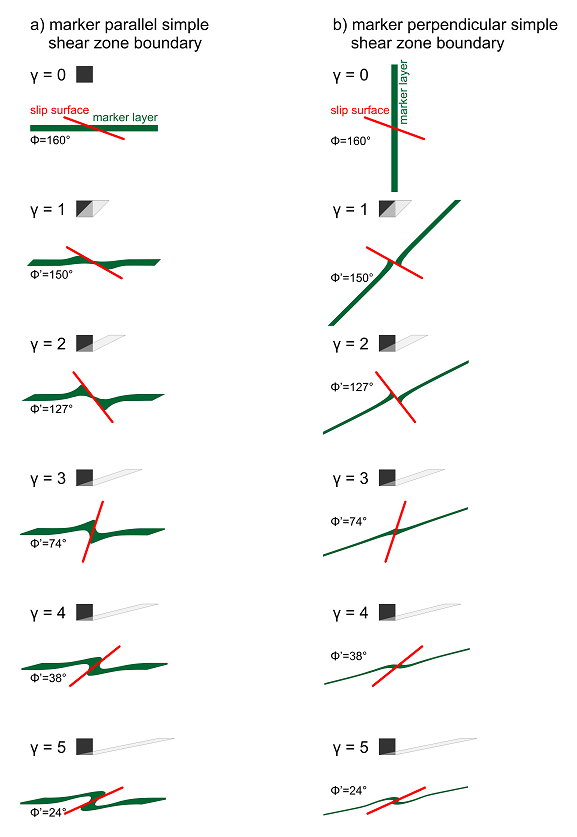
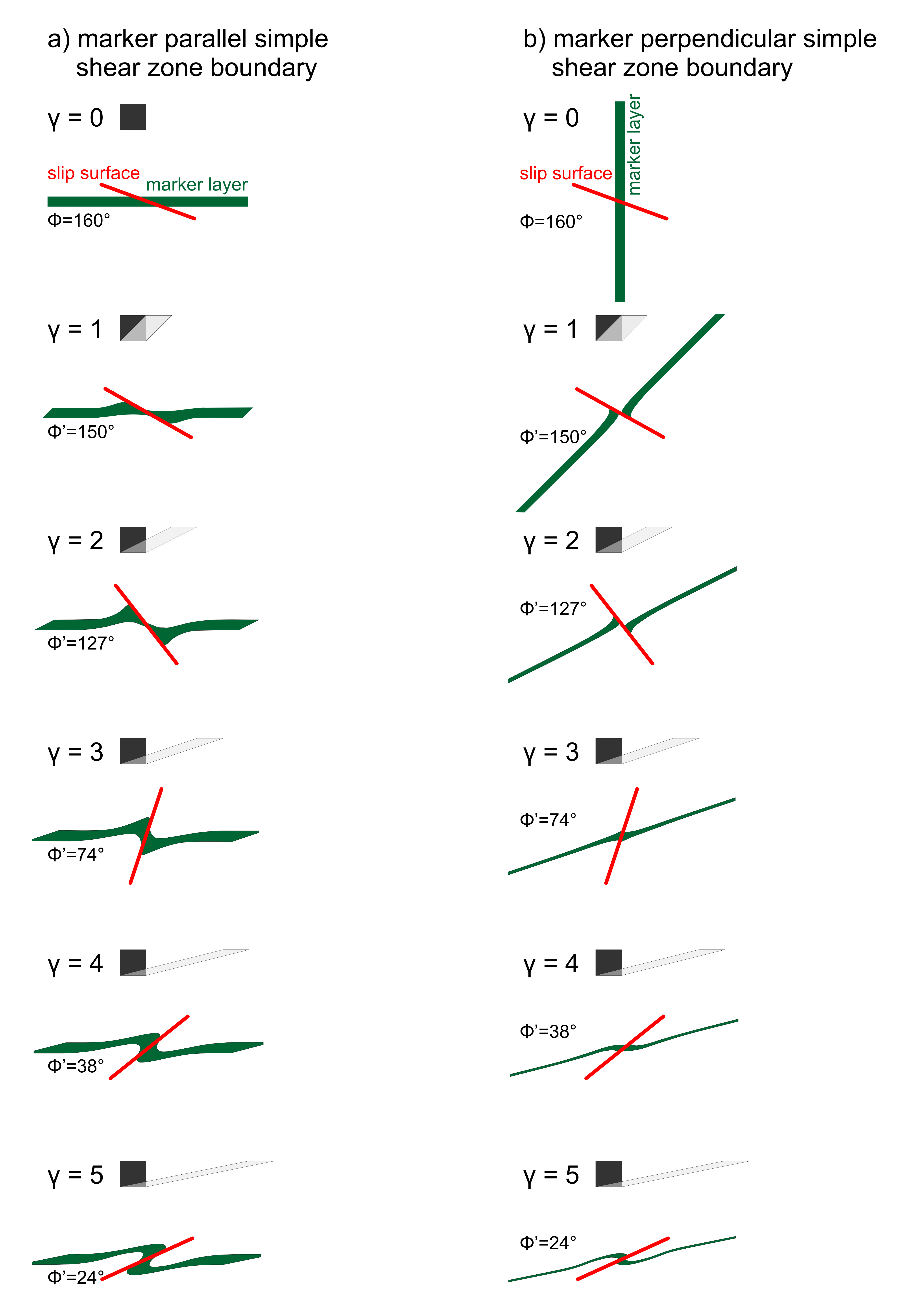
In what follows we investigate the structural development of a shear zone parallel (Fig. 5a) and perpendicular (Fig. 5b) green marker layer cut by a slip surface initially oriented at Φ = 160°. During shearing the slip surface rotates into the shear direction changing the instantaneous shear sense from syn- to antithetic at 135° (i.e. σ1) and from anti- to synthetic at 45° (i.e. σ3). The rotation rate is indistinguishable from that of a passive marker line. The progressive development of the structures up to a shear strain of γ = 5 in Figure 5a is well understood and similar models have been described by means of analogue forward and dynamic reverse numerical modelling (Exner et al., 2004; Kocher and Mancktelow, 2005). However, the structure in Figure 5b has a distinctly different evolution. The physical parameters, mathematical model, boundary conditions, initial orientation and progressive rotation of the slip surface are identical to the model in Figure 5a. The only difference is that the deformation of a passive marker layer with the same thickness but oriented perpendicular to the shear zone has been observed. The major differences during progressive shearing are, that the initially perpendicular passive marker layer is subjected to rotation and to stretching and thinning. The maximum rotation rate is at the beginning of the model, when the layer is oriented at 90° with respect to the shear zone boundary. During rotation towards the fabric attractor (i.e. the direction parallel to the shear zone boundary) the rotation rate decelerates. At the same time, the green marker layer is stretched during rotation. The maximum instantaneous stretching rate is at an orientation of 45° with respect to the shear zone boundary, when the layer is parallel to σ3. The structures resulting from shear zone parallel and normal markers at low shear strain (e.g. γ = 1 in Fig. 5a and b) look qualitatively totally different. For example the structure in Figure 5a at a shear strain of γ = 1 would be classified as a shear band. However, the structure developed under exactly the same parameters and boundary conditions but with an initial shear zone perpendicular marker (Fig. 5b) would be referred to as negative slipped flanking fold. Interestingly, the structures become qualitatively more and more similar at larger shear strains: at γ = 4 both structures in Figure 5a and b are no slip flanking folds and at γ = 5, positive slipped flanking folds.
Figure 5. Progressive deformation (dextral simple shear, γ = 1-5) of a marker layer
Progressive deformation (dextral simple shear, γ = 1-5) of a marker layer a) parallel and b) perpendicular to the shear zone boundary. The slip surface has an initial orientation of 160° with respect to the fabric attractor. Note, that the structures in a) and b) become increasingly similar with increasing strain.