Definition of extensional and contractional offset
In structural geology dip-slip faults can be classified into reverse and normal faults. Considering the Earth’s surface as a reference frame with zero shear stress, Anderson´s fault theory predicts that normal faults occur where the greatest principal stress is vertical and reverse faults occur where the least principal stress direction is vertical (Anderson, 1951). A normal fault occurs when the crust is extended and a marker horizon sub-parallel to the Earth’s surface reference frame (x – horizontal, y - vertical downwards, Fig. 1) would record extensional offset (the length l0 before deformation is shorter than the length l after faulting, Fig. 1a). In hydrocarbon exploration missing sections identified in wells are traditionally interpreted as the expression of a normal fault (Tearpock and Bischke, 2003). A reverse fault is indicative of shortening of the crust, and the marker horizon records contractional offset (l0 > l). A repetition of the stratigraphy in well data is generally considered to be indicative of reverse faults (Fig. 1b).
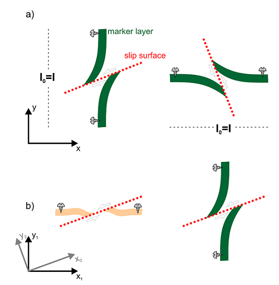
Figure 1. Extensional (normal) and contractional (reverse) offset

a) Extensional (normal) and b) contractional (reverse) offset of a stratigraphic layer parallel to the Earth’s surface. The reference frame is generally considered to be the Earth’s surface. In subsurface geology, normal faults record a missing section, whereas along thrust (reverse) faults the section is repeated.
The discrimination between extensional and contractional offset along secondary finite slip surfaces in ductile flow is more ambiguous because the offset is strongly dependent on the chosen reference frame and the angle between the marker and the slip surface. Considering the offset along an isolated slip surface, which creates a heterogeneous perturbation strain in the otherwise homogeneously deforming host rocks (Passchier et al., 2005), an offset marker line would experience neither extension nor shortening in the far-field (except from deformation by the homogeneous background strain). Whether the structure resembles a normal or reverse fault is strongly dependent on the chosen reference frame (Fig. 2a). Quantitative kinematic and mechanic studies of shear sense indicators in ductile shear zones (e.g. Ramberg, 1975; Simpson and De Paor, 1993; Schmid and Podladchikov, 2004 and many others as well those cited above) frequently consider a reference frame, where the Cartesian coordinate system is parallel to the shear zone boundary (x1-y1 in Fig. 2b). In these studies marker lines are generally considered to be parallel to the shear zone boundary. Using such a reference frame the left structure in Figure 2b would indicate an extensional offset. Other mathematical solutions, which are for examples based on linear elastic fracture mechanics theory (e.g. Pollard and Segall, 1987; Martel, 1997), consider a Cartesian coordinate system, which is parallel to the slip surface or to the long axis of an elliptical inclusion (x2-y2 in Fig. 2b). Whether a marker horizon is missing or repeated in a section parallel to the y-axis of the coordinate system is again determined by the chosen reference frame (compare the right structure in Fig. 2b choosing x1-y1 or x2-y2 for coordinate system).
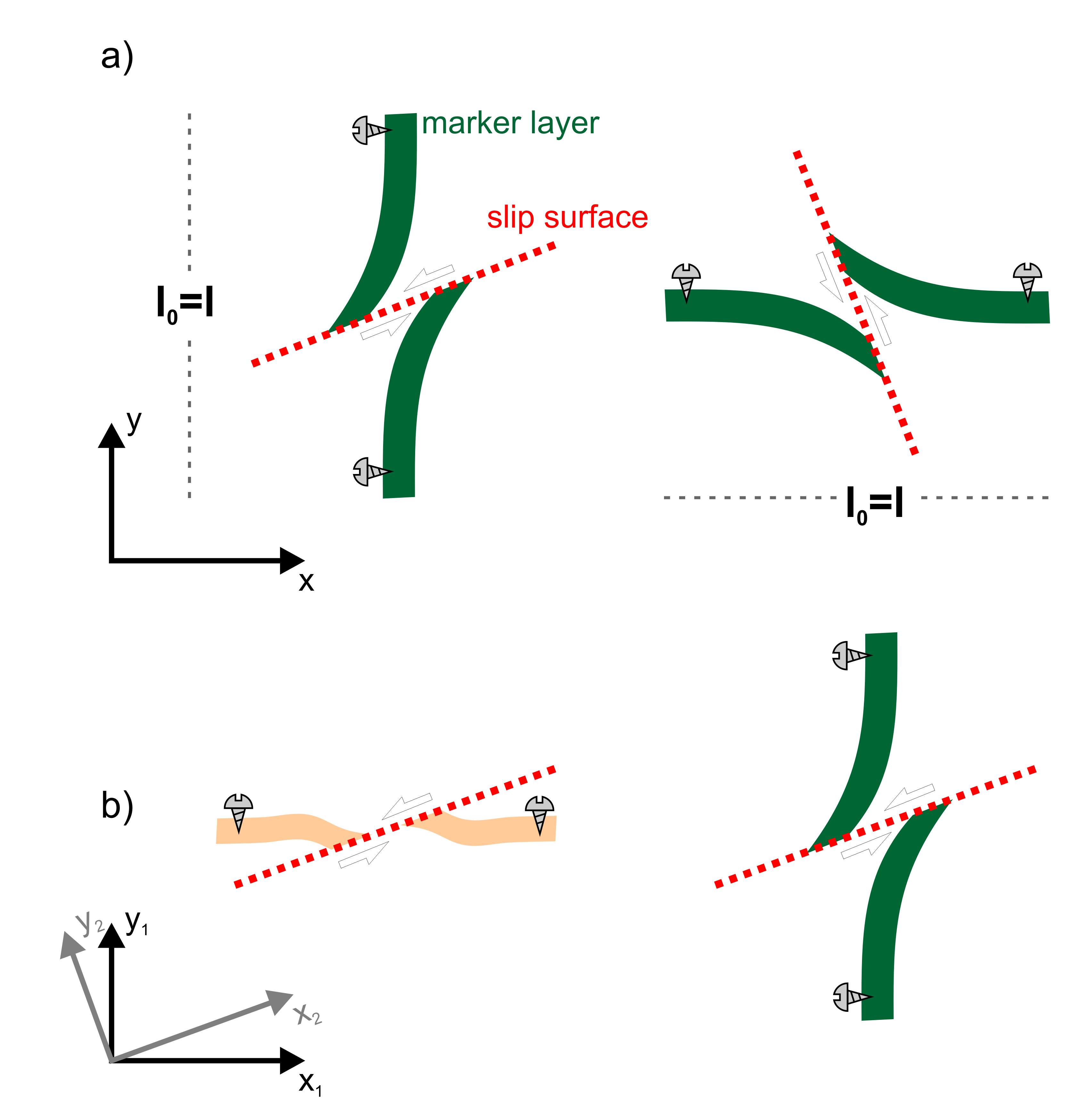
Figure 2. Offset along a slip surface observed in a Cartesian x-y coordinate system
a) Extensional (left) and contractional (right) offset along a slip surface observed in a reference frame defined by a Cartesian x-y coordinate system. Note, that there is no length change of the marker in the far field. b) In a reference frame defined by a Cartesian x1-y1 coordinate system, both, the left and the right structures, record an extensional offset of the marker layers. However, in a reference frame defined by a Cartesian x2-y2 coordinate system (i.e. parallel to the slip surface), the left structure records a “missing section”, whereas the right structure creates a repeated marker layer.
In quantitative kinematic interpretations the frequently used assumption of a reference frame parallel to the shear zone boundary is certainly a good choice since this is always a non-rotating direction (i.e. eigenvector of flow, Bobyarchick, 1986). All material lines rotate toward the constant length (simple shear) or extending line (general shear) of no instantaneous angular velocity. This vector is also sometimes referred to as either extensional flow apophysis (Ramberg, 1975) or the fabric attractor (Passchier, 1997). Therefore marker lines parallel to this direction are also a plausible assumption but it is important to note, that the fabric attractor is only parallel to the shear zone boundary in simple shear or narrowing shear zones. In broadening shear zones or dilatant flow, the shortening eigenvector of flow is parallel to the shear zone boundary but the fabric attractor is oblique to this direction, at an angle which depends on the kinematic vorticity number of the flow (Simpson and De Paor, 1993; Passchier, 1997). Additionally, other markers like veins or secondary foliations, which make an angle with the shear zone boundary, may be offset by slip surfaces. We therefore discuss first the instantaneous deformation of two marker lines, one parallel and the other perpendicular to the shear zone boundary. Furthermore, we demonstrate structures that develop during progressive deformation where the slip surfaces and marker lines, which are perpendicular to the fabric attractor, rotate and where the slip surface may change the local sense of shear depending on their orientation to the principal stress directions.