This set-up (Fig. 11) was designed by Le Calvez and Vendeville (1996) as an attempt to combine the advantages of (1) a basal velocity discontinuity to localize offset faults and (2) the cushioning effect of a low-strength viscous layer to allow faults to propagate and interact freely. This set-up was tested only for relay zones between normal faults.
Figure 11. Experimental set-up used by Le Calvez and Vendeville
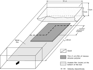
Experimental set-up used by Le Calvez and Vendeville (1996) to model graben relays using a sand layer, a weak basal viscous layer, and a basal plastic sheet. Note that only the center of the model comprises the weak viscous layer.
Like Faugère and Brun's, and Sims et al.'s models, this set-up required the presence of a dog-leg shaped velocity discontinuity at the model's base. As in Sims et al.'s model, the design involved a thin viscous layer below the base of the brittle layer. However, the viscous layer was located only in the central part of the model and the deformation rate was low enough (2 mm.h-1) to allow for full decoupling between the model's base and the brittle layer. According to this design, the lateral parts of the model did not comprise a viscous layer: the brittle layer lay directly on top of the velocity discontinuity. This design forced normal faults to form at predetermined location (hence with predetermined offset) in the lateral parts of the model. After normal faults formed in the lateral areas, they propagated along strike into the model's center, the area underlain by the weak viscous layer and in which faults could freely propagate irrespective of the location of the velocity discontinuity below the viscous layer.
In all experiments, grabens formed first in each lateral part of the box, where the viscous layer is absent (Fig. 12). The graben faults rooted at depth on the velocity discontinuity. Like in experiments by Faugère and Brun (1984), the grabens were asymmetric and bounded on one side by one permanent fault, and on the other side by transient faults.
Figure 12. Model by Le Calvez and Vendeville
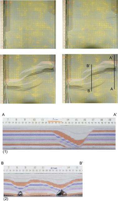
Overhead photographs and N-S cross sections in model by Le Calvez and Vendeville (1996). Faults form first in the lateral regions of the model, where the lubricating basal viscous layer is absent, then propagate along strike into the mode's center, above the lubricating viscous layer. Grabens are asymmetric in the lateral parts (Cross section 1), and symmetric in the model's center (Cross section 2).
Each graben then propagated along strike toward the center of the model, where the thin viscous layer decoupled the brittle layer from the model's base. Unlike in the lateral parts of the box, where the viscous layer is absent, grabens in the center tended to be more symmetric (Fig.12). Unlike in experiments conducted using the two previous set-ups (e.g., Faugère and Brun, 1984; Vendeville, 1991; and Sims et al., 1999), the faults' traces and location in the model's center did not follow the velocity discontinuity located below the viscous layer. The low displacement rate allowed the viscous layer to fully decouple the brittle layer from the model's base in the center. Varying the shape of the velocity discontinuity, where the viscous layer was present did not change the grabens' geometry in the central area.
Results show that fault orientation and linkage vary with varying the amount of graben offset. Grabens having small offset propagate perpendicularly to the direction of regional extension and fault slip gradually decreases along strike, toward the model's center. With additional extension and syntectonic sedimentation, faults eventually hard-link. Grabens having moderate offset widen as they propagate toward each other and faults trend oblique with respect to the direction of extension. Faults soft-link and fault slip gradually decreases along strike. Displacement is transferred between overlapping faults by distorting fault ramps in the intervening blocks. Where graben offset is initially large, fault displacement is not transferred by soft-linked faults and distorted ramps. Instead, a new transtensional graben forms oblique to the direction of regional extension, and acts as a transfer structure between the two offset grabens. The formation of a new oblique transfer structure reflects a critical size for the rock volume between offset grabens (hence the graben offset) above which soft linkage and block distortion alone cannot accommodate deformation.
The main flaw with the two previous model designs was that the presence of a transverse velocity discontinuity dictated the location, orientation, and sense of asymmetry of faults in the overlying brittle layer. The design by Le Calvez and Vendeville (1996) circumvents this flaw by effectively insulating the brittle layer from the transverse velocity discontinuity located in the model's center. Because faults could freely propagate along strike, the interaction between the two offset grabens was controlled solely by their mutual influence on each other's stress state.
Mechanically, this design also respects the main rheological characteristics of the natural prototype: the model comprises a strong brittle layer overlying a weaker viscous layer. However, this design does not incorporate some of the boundary conditions proper to the natural prototype. Because the viscous layer is thin, isostatic rise or subsidence of the faults blocks remained severely limited. Furthermore, the influence of the velocity discontinuity in the lateral areas of the model imparted some asymmetry to the grabens. Although grabens tend to become more symmetrical as they propagate along strike above the lubricating viscous layer, the asymmetry in the lateral areas is likely to affect the fault pattern and evolution even in the model's center.