This design (Fig. 13) departs radically from the three above designs because it does not rely on the presence of a basal velocity discontinuity (Le Calvez and Vendeville, 2000). Instead of propagating localized deformation from the base upward into the brittle layer, this design allows to make the brittle layer locally weaker in order to trigger faults or grabens at predetermined location. This set-up was used only to model relay zones between offset grabens. It has not yet been tested on experiments simulating pull-apart basins between offset strike-slip faults.
Figure 13. Experimental set-up used by Le Calvez and Vendeville
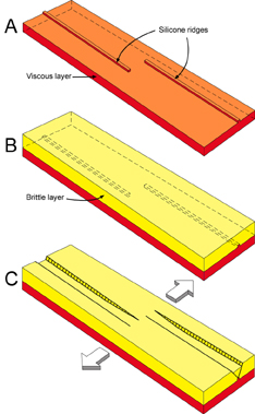
Experimental set-up used by Le Calvez and Vendeville (2000) to model graben relays using a thick layer of viscous silicone overlain by a thick sand layer. Two narrow ridges of silicone at the base of the sand layer trigger nucleation of two offset grabens.
The models were constructed and deformed in a large box (152-cm long and initially 50-cm wide; Fig. 13). The models comprised a 2.0-cm-thick layer of Newtonian transparent viscous silicone polymer (El Polymer NA, a Polydimethyl Siloxane manufactured by Wacker Silicones, U. S., whose properties have been described in detail by Weijermars in 1986) (density of about 950 km.m-3 and effective viscosity of about 6 x 10⁴ Pa.s at a strain rate of 10-4 s-1), representing the salt layer (or lower continental crust for crustal-scale models), overlain by a thick (i.e., 5-10 cm) layer of dry sand (angle of internal friction of 25° to 30°, low cohesion, and density ranging from 1500 to 1700 kg.m-3), representing the brittle sedimentary overburden (or upper crust for crustal-scale models). After deposition of the viscous layer and before deposition of the sand layer, two long and low ridges of silicone (about 0.5-mm high and 1-cm wide) were laid on top of the viscous layer. The sand cover was therefore locally thinner (by 5 or 10%) above the silicone ridges (Fig. 14). Each one of the two ridges extended across half the model's length. The ridges were parallel to the moving walls used to impose extension, and were laterally offset. The amount of offset between the ridges varied between experiment in order to test its influence on the deformation pattern in the relay zone.
Bases of scaling theories were thoroughly described by Hubbert (1937, 1951).
Deformation was imposed by slowly moving the two endwalls at a low displacement rate (0.5 mm.h-1). As the two endwalls moved apart, the model spread under the effect of its own weight and deformed by thin-skinned extension. The viscous layer flowed while the brittle cover faulted. In the absence of silicone ridges, faults in the brittle layer would have nucleated either randomly or, more likely, close to the moving walls. However, because the brittle layer was initially locally thinner, hence weaker, above the silicone ridges, normal faults formed there (Fig. 14). The silicone ridges acted as triggers to nucleate the grabens at predetermined locations. Once the faults nucleated, the fault planes themselves controlled subsequent deformation because of the stress softening associated with faulting.
Figure 14. Schematic strength profiles
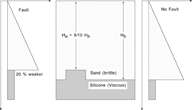
Schematic strength profiles illustrating that a silicone ridge (height: 1/10th of the sand-layer thickness) lowers locally the strength of the brittle layer by 20% and therefore nucleate faulting there.
The advantage of using this set-up is that although the ridges represented instabilities large enough to nucleate faults above them, these instabilities remained small compared with the fault planes. During subsequent extension faults are therefore free to propagate and interact freely, irrespective of the presence of the trigger ridges. Although the ridges are efficient initial triggers, the instabilities they represent are too small to affect deformation once fault planes have formed. On this regard, the role of the silicone ridges is comparable to weak nodes often inserted in finite-elements numerical simulation to localize faults of folds at chosen location.
We conducted a series of 19 experiments using the above design. In this section, we present only a summary of the main results (Figs. 15 to 17). In all models, a graben nucleated on top of each trigger ridge. Each graben rapidly propagated along the entire length of the underlying ridge. During subsequent extension, the graben tips propagated along strike, beyond the tips of the underlying ridges. Depending on the amount of initial offset between the ridges (hence between the grabens), the grabens influence each other's propagation in various ways. Grabens having large imposed offsets progressively curved one toward the other and remained soft linked (Animation 1). The relay zone was wide and long (linearly proportional to the initial offset) and included fault blocks rotated around vertical and horizontal axes (Fig. 15). By contrast, faults bounding grabens having smaller imposed hard linked or even intersected one another, forming hourglass structures in the relay zone (Animation 2). The relay zone was narrow. In all models, the fault throw progressively decreased along strike, toward the relay zone (Fig. 16). Most grabens were symmetrical, with younger faults forming within the original graben block. Normal faulting thinned the graben floor, allowing the underlying viscous layer to respond isostatically by forming rising reactive diapirs (as described in Vendeville and Jackson, 1992). Like fault throw, the intensity of diapiric rise decreased along strike, toward the relay zone (Fig. 17).
Figure 15. Model of graben relay by Le Calvez and Vendeville
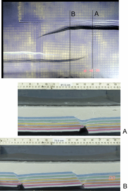
Overhead photograph and cross section of a model of graben relay by Le Calvez and Vendeville (1999). Cross sections: A: far from the relay zone; B: in the relay zone. Note that graben fault traces curve gently one toward the other, that fault slip progressively decreases toward the relay zone, and that the viscous layer rose diapirically beneath the grabens.
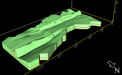
Figure 16. Model by Le Calvez and Vendeville
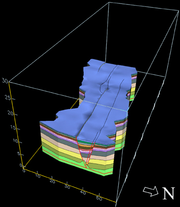
3-D visualization of a model by Le Calvez and Vendeville (1999) showing the entire model (viscous and brittle layers). Note the progressive change in fault throw along strike.
Figure 17. Model by Le Calvez and Vendeville
3-D visualization of a model by Le Calvez and Vendeville (1999) showing the top of the viscous layer and illustrating the progressive decrease in diapiric rise toward the relay zone.
Animation 1. Model simulation with large initial graben offset
Overhead view of model deformation through time showing soft-linked grabens (large initial graben offset).
Click on text to view animation.
Animation 1. Model simulation with small initial graben offset
Overhead view of model deformation through time showing hard-linked grabens (small initial graben offset).
Click on text to view animation.
This design differs from all other designs because it does not involve upward propagation of basal discontinuities from the model's base. Models have rheological and boundary conditions similar to those of the natural prototype. The model comprises a weak viscous layer overlain by a stronger brittle layer. Fault blocks can rise, subside, or rotate around vertical and horizontal axes in response to deformation. Once they have nucleated, the faults can freely propagate along strike. To be reliable, this design requires that the silicone ridges act as temporary instabilities that control the location of the first faults during their nucleation, while the ridges do not interfere with deformation once the faults have formed. We conducted several experiments to test for possible influence of the ridges after nucleation of the main faults. In nature, faults are expected to nucleate as short segments that subsequently propagate along strike.
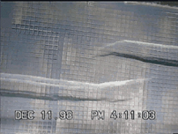
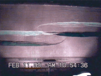
Figure 18. Photographs of the model surface
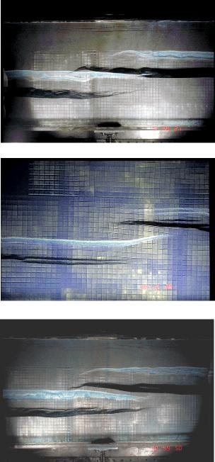
Photographs of the model's surface for three experiments having similar graben offset and sand thickness but varying amounts of underlap or overlap (Le Calvez and Vendeville, 1999). A: 40 cm underlap; B: no overlap - no underlap; C: 40 cm overlap. Note that A and B deformed similarly but that the presence of a large overlap influences fault propagation and changes the geometry of the relay zone.
We therefore tested whether changing the length of the trigger ridges, which, to some extent, can be regarded as equivalent to the length of the initial fault segments in nature, could affect the deformation outcome. We conducted three experiments (Fig. 18) having identical characteristics (thickness, displacement rate, and amount of finite extension) but having silicone ridges of varying length. In one model (Fig. 18A), the ridges had a large underlap: their tips were 40 cm apart. In another model ((Fig. 18B), the tips of both ridges were aligned near the model's center. In a third model (Fig. 18C), the ridges overlapped by 40 cm.
The deformation patterns in the first two models (Figs. 18A and 18B: underlap and aligned ridge tips) are similar. In the model having in an underlap configuration (Fig. 18C), where the initial fault segments were short and far apart, faults first propagated along strike with a straight trace. Faults from the offset grabens started to interact and curve only once their tips had propagated beyond each other, past the model's center. This observation explains the similar pattern between models where the original ridges' tips were located far apart or were aligned (Figs. 18A and 18B). The ridges' tips did not interfere with the along-strike propagation of the graben faults.
By contrast, in the model in Figure 18C, the presence of overlapping ridges appears to have influenced fault propagation: instead of starting to interact near the model center (where the tips of the two offset grabens are aligned), the graben faults propagated in a straight manner up to the tips of the underlying ridges. The presence of overlapping ridges clearly influenced the deformation pattern in the relay zone. For this reason, our series of experiments used only set-ups where the trigger ridges were underlapping or had aligned tips.