This set-up (Fig. 9) was designed by Sims et al. (1999) to alleviate some of the main flaws of pull-apart models using a basal sheet, especially the rooting of fault planes into the transverse velocity discontinuity. Like Faugère and Brun (1984), Sims et al. (1999) used a basal plastic sheet, on edge of which was attached to a mobile wall. On the other side, the sheet's edge was dog-leg shaped and comprised two edges parallel to the lateral walls (to induce strike slip) linked by a transverse edge oblique to the direction of imposed displacement. Unlike the previous models, where the brittle layer rested directly onto the model's base and basal plastic sheet, Sims et al.'s model comprised a thin (0.5 to 1.0 cm), tabular layer of viscous silicone polymer located between the base and the brittle layer and covering the entire model area. Because the applied deformation rate was high (10 cm.h-1) the viscous layer was strong enough to allow for some amount of coupling between the basal sheet and the brittle layer and therefore induce the formation of two laterally offset strike-slip zones in the brittle layer.
Figure 9. Experimental set-up used by Sims
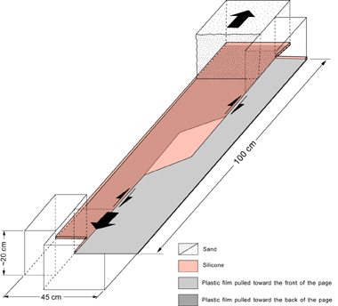
Experimental set-up used by Sims et al. (1999) to model pull-apart basins using a sand layer, a strong basal viscous layer, and a basal plastic sheet.
In all experiments, faulting initiates as Riedel R shears oriented sub-parallel to the oblique, transverse edge of the plastic sheet (Fig. 10). Formation of the Riedel R shears is closely followed by antithetic, Riedel R’ shears and synthetic P shears linking with the R shears to form fault-bounded horses in strike-slip duplexes. The duplexes rotate clockwise, synthetic to displacement along the primary strike-slip faults. Formation of linear D shears follows the formation of antithetic R’ shears. Basin subsidence begins with local formation of normal faults, the onset of dip slip on existing R and R’ shears, or both (Fig. 10). Normal displacement varies along strike to create asymmetric sub-basins with basin asymmetry switching side along strike. Large basins are elongate and bound on one side by a strike-slip faults and normal faults on the opposite sides, or by strike-slip fault and normal or oblique-slip faults on the opposite sides (Fig. 11). The basin floor has a trapdoor geometry, where the basin is bounded on all but one side by faults, with the remaining side operating as a hinge. Cross sections (Fig. 10) indicate that the main faults formed above or near the basal velocity discontinuities.
Figure 10. Overhead photograph and cross sections in a model by Sims et al. (1999). The overhead photograph shows the first faults whose traces are parallel to the underlying velocity discontinuity. Cross sections also show that faults form near the basal discontinuity (arrows).
Sims et al. (1999)'s design represents an improvement of previous designs because it incorporates the presence of a viscous layer beneath the brittle cover. Ideally, the viscous layer may be considered as an analog for the ductile lower crust or for an evaporitic décollement at the base of the sedimentary cover. However, the high deformation rate used during these experiments makes this viscous layer much stronger than what a properly dynamically scaled analog for either the lower crust or a stratigraphic décollement would be. In order to properly simulate such viscous layers, the model would have to be deformed at a much lower rate. The quandary faced by modelers is twofold. In order to transmit localized strain from the basal sheet to the brittle layer, the basal viscous layer must be strong enough, hence deformed at a high strain rate. Whereas in order to properly simulate a décollement or the lower crust deformed at typical geological strain rates, the model must be deformed at rates so low that the viscous layer would effectively fully decouple the brittle sand layers from the model's base. Practically, such decoupling by the weak layer would not transmit the velocity discontinuity from the model's base to the overlying brittle layer, which would therefore deform in response to the movement of the endwalls and sidewalls only, rather than to the movement of the basal plate. As a result of the high strain rate, the models by Sims et al. (1999), like those by Faugère and Brun (1984), deform first by formation of faults located above the transverse velocity discontinuity. The transition zones between the two strike-slip faults forms before the strike-slip faults themselves (Fig. 10).
In addition, most faults form above or near the basal velocity discontinuities, including above the transverse boundary (Fig. 10). According to this scheme, the set-up, once again, constrains not only the location of the two offset strike-slip faults, but also that of the faults in the accommodation zone. There, faults do not form solely in response to the interaction between the offset strike-slip faults: instead, their location and orientation match those of transverse edge of the underlying basal sheet.
Finally, because the basal viscous layer was thin and strong, the amount of vertical subsidence and uplift of the base of the brittle layer remained limited, which makes these models applicable to geological settings involving thin décollements only, and not analogous to lower-upper continental crust.