This type of set-up has been used to model 2-D extensional systems (McClay and Ellis, 1987; Faugère and Brun, 1984: Fig. 4), relay zones between offset normal faults (Vendeville, 1991: Figs. 7 and 8) and pull-apart basins located between offset strike-slip zones (Faugère and Brun, 1984: Figs. 5 and 6). In all experiments, a thin sheet of non-stretchable acetate plastic was placed on the model's rigid base. One end of the plastic sheet was attached to a moving wall. The models were built entirely of layered dry sand, having low cohesion and an angle of internal friction near 30˜. One part of the sand layer rested on the plastic sheet. The other part, where the sheet was absent, rested directly on the rigid base.
Figure 4. Experimental set-up
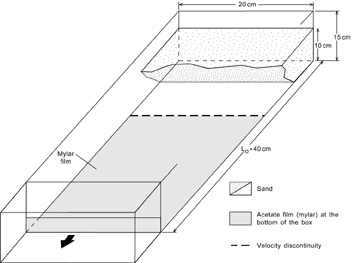
Experimental set-up used by Faugère and Brun (1984) to model pure extension using a sand layer resting on a basal plastic sheet.
Figure 5. Experimental set-up
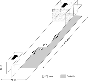
Experimental set-up used by Faugère and Brun (1984) to model pull-apart basins.
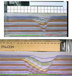
Figure 6. Cross sections in a model by Faugère and Brun
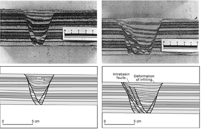
Photographs and line drawing of cross sections in a model by Faugère and Brun (1984) showing the graben asymmetry, including the presence of one permanent faults (right-hand side) and transient faults (left-hand side).
Deformation was induced by pulling the moving endwall and thereby pulling the attached acetate sheet. The purely extensional models evolved as follows. First, a pair of normal faults nucleated above the edge of the basal plate (the velocity discontinuity). The fault located above the moving sheet remained active throughout the entire experiment. This fault and its footwall remained attached to the moving basal sheet. On the other side, the fault located above the rigid model base ceased to slip once the velocity discontinuity moved farther away. A new fault nucleated above the velocity discontinuity and split the triangular graben block. This process was repeated during additional extension, as faults above the rigid model base slipped only for a short period, while their base was near the velocity discontinuity. In experiments having no concurrent sedimentation, the graben block became smaller until the two halves of the original sand layer became disconnected. In experiments having syntectonic sedimentation filling the graben trough, new faults on the fixed side formed continuously above the velocity discontinuity. The overall resulting geometry was that of an asymmetric graben: above the basal plastic sheet, one permanent fault rooted at depth on the velocity discontinuity and its footwall remained continuously attached to the moving basal sheet; above the fixed model base, the graben was bounded by a series of transient faults younging toward the velocity discontinuity, each fault remaining active only shortly. The sense of asymmetry was directly related to the geometry of the basal sheet, with the permanent fault located above the sheet. Flipping the side where the basal sheet lay led to an opposite sense of asymmetry.
Figure 7. Model by Vendeville
Overhead photographs of a model by Vendeville (1991) simulating graben relays. Extension was E-W.
Figure 8. Cross-sections in a model by Vendeville
Cross-sections in a model by Vendeville (1991) simulating graben relays. Top: N-S cross section intersecting one graben. Bottom: E-W cross section intersecting the relay zone. Note that all faults root at depth on the velocity discontinuity.
This simple 2-D geometry was further developed into 3-D set-ups by Faugère and Brun (1984) to model pull-apart basins and by Vendeville (1991) to model relay zones between extensional grabens (Figs. 7 and 8). In these set-ups the edge of the basal plastic sheet was dog-leg shaped, having (1) for pull-apart basins, two edges parallel to the lateral walls (thus inducing strike-slip movement) linked by one transverse edge perpendicular to the direction of displacement, or (2) for extensional relay zones, two edges perpendicular to the lateral walls (inducing local extension) linked by one transverse edge parallel to the direction of displacement, As in the purely extensional models, the active faults always nucleated on the basal velocity discontinuities. Strike-slip faults nucleated on top of the edges parallel to the lateral walls, whereas normal faults nucleated on top of edges perpendicular to the imposed motion. In both models, extensional structures were the first structures visible from top views, whereas strike-slip zones appeared later, which suggests that more strain was required for strike-slip zones to form. Also, all faults rooted at depth along the edges of the basal sheet (Figs. 6 and 8), whether these faults were parallel or perpendicular to the direction of imposed displacement. Although faults at depth rooted on the velocity discontinuity, their surface traces did not strictly follow the geometry of the basal sheet. Fault planes were curved in both plane view and cross section. The extensional regions of the models were characterized by asymmetric grabens whose sense of asymmetry was directly related to the geometry of the basal sheet.
Although the above models successfully formed linked strike-slip and extensional fault zones, their applicability to the natural prototype is limited by several observations. First, every active fault formed above the basal velocity discontinuity, including within the relay zone or in the pull-apart basin. The geometry of the transverse edge of the basal sheet entirely controlled the location of faults in the transition zone. In other words, the location and geometry of structures in the interaction region (pull-apart basin or relay zone) results from the nucleation and upward propagation of faults from the velocity discontinuity, rather than the result of interaction between the two main offset faults. Indeed, changing the orientation of the transverse velocity discontinuity changed the structural pattern within the relay zone or pull-apart basin. Second, the mechanical properties of the models were not properly scaled equivalents of the natural prototype. In nature, the brittle layer rests on a weaker viscous layer. In the models, the brittle layer overlay a stronger rigid base (model’s base or basal plate) onto which it remained effectively attached during deformation. The only part of the brittle layer that deformed was narrow, triangular in cross sections, and confined to the area located immediately above the velocity discontinuity (graben or strike-slip zone). Third, the use of an extensional velocity discontinuity has one structural inevitable side effect, asymmetry. One side of the graben is bounded by one permanent fault, whereas the faults on the other side are continuously replaced by younger faults. Fourth, designs using a basal plate do not allow fault blocks to rise or subside isostatically. The base of the brittle layer remains flat and horizontal, bounded to the model's base. Overall, the main flaw of these experimental designs is that although the experiment is meant to elucidate how faults interact along strike, its very design entirely dictates the resulting structural pattern. This flaw is particularly well illustrated by the fact that although the goal of the pull-apart experiments was to investigate the formation of transtensional faults in response to motion along two strike-slip faults, the transtensional structures in the model formed before the strike-slip faults formed.