an analogue modelling approach
Experimental results (continued)
Multiple rifting - Experiment 78
In experiment 078 the model underwent two stages of rifting. Extension during the first rift event amounted to a little over 12% and resulted in the development of conjugate normal fault systems in the brittle layer (Fig. 2). Grabens were filled with granular material and overlain by additional brittle and viscous material (Fig. 2). Subsequently the model underwent a second rifting event with the same direction of extension. Fig. 13 shows the surface evolution after 6.5% extension during the second rifting event, while the evolution of structures in four cross-sections is shown in Fig. 14. The first frame in Fig. 14 shows the conjugate normal faults that formed during the first rifting event. Extension during the second rifting event caused immediate reactivation of the pre-existing normal faults. In the brittle-viscous domain with only one viscous layer, faults propagated toward the surface. In the domain with two viscous layers, however, faults only propagated upward as far as the interbedded viscous layer. New faults formed in the upper brittle compartment, but sideways displaced with respect to faults in the lower brittle compartment. Grabens in the upper brittle compartment formed in those areas where horsts formed in the lower brittle compartment. Faults acquired a listric shape with progressive extension and fault-bounded blocks underwent rotations about a horizontal axis. Block rotations in the lower brittle department influenced as yet unfaulted domains in the upper brittle compartment and locally created new, strongly curved faults in the upper brittle compartment along which small fault blocks are squeezed upward. These curved faults have a dip-slip component at its lower end and a reverse-slip component at the surface.
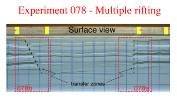 |
| Figure 13. Surface photograph of experiment 078 after 6.5% extension during the second rifting event. Black dashed lines indicate major transfer zones located above the interbedded viscous layer. Dashed red rectangles indicates areas analysed by X-ray tomography. |
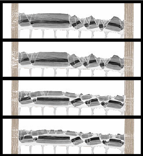 |
| Figure 14. Successive vertical CT images through experiment 078 (domain 078a, see Fig. 13): two sections cross the domain with only a basal viscous layer overlain by brittle layers (upper two images), and two sections the domain with two viscous layers (lower two images). Corundum is dark grey; sand is medium-grey, and viscous PDMS is light-grey. After the first rifting event the width of model was 23 cm and the height was 3.5 cm. Extension increment between frames is 5 mm. (Select image to view movie) |
Figure 15 shows the progressive evolution of structures in surface view and illustrates the distinct fault pattern between the domain underlain by one viscous layer (large grabens) and the domain underlain by two viscous layers (smaller grabens). In the former domain the location of the grabens is controlled by the faults that formed during the first rifting event, and the initial width of the grabens is determined by the depth to the basal viscous layer. In the latter domain, however, the interbedded viscous layer did not allow the reactivated normal faults in the lower brittle compartment to reach the surface. Fig 16 shows the 3D progressive evolution of part of experiment 078. As in the previous experiment, the location and orientation of extensional transfer zones is related to the shape of the interbedded viscous layer (Fig. 17). However, in contrast to experiment 77 the normal faults in the lower brittle compartment do not die out along strike, but continue into the domain with only a basal viscous layer. Consequently, sections through the lower brittle compartment do not show a transfer zone (Fig. 18 & 19). Figs. 20 and 21 show the structures in experiment 078 at a more advanced stage of multiple rifting (after 15% extension during the second rifting event).