an analogue modelling approach
Experimental results
Multiple rifting - Experiment 78 (continued)
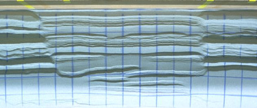 |
| Figure 15. Movie showing surface evolution of experiment 078. Note the difference in graben width between domain with interbedded viscous layer (cf. Fig. 2 for its location) and adjacent domains. Initial grid spacing on surface was 4 cm. Extension increment between frames is 5 mm. (Select image to view movie) |
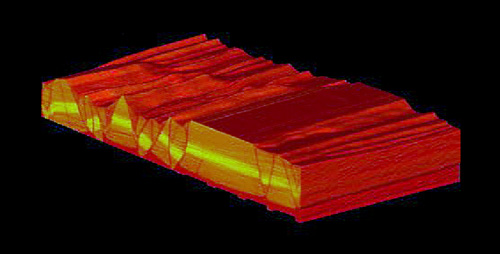 |
| Figure 16. Movie of 3D evolution with time of experiment 078 (domain 078b, cf. Fig. 13) showing the development of a transfer zone oblique to the extension direction. Each frame shows a cut-out 3D view that consists of 80 serial cross sections each representing a 2 mm thick CT slice. Extension increment between frames is 1 cm. (Select image to view movie) |
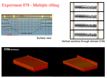 |
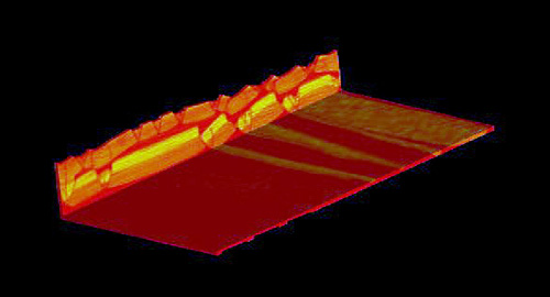
| Figure 17. Structures in experiment 078 after 6.5% extension during second rifting event, illustrated by surface photograph, vertical sections and two cut-out 3-D perspective views. Transfer zones are related to the shape and position of the interbedded viscous layer. |
 |
| Figure 18. Horizontal sections through 3D cut-out perspective view showing oblique transfer zone after 6.5% extension during the second rifting event (domain 078b; see. Fig. 17). (Select image to view movie) |
 |
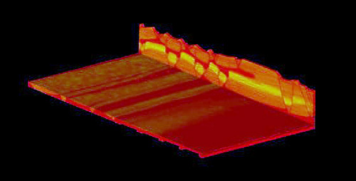
| Figure 19. Successive horizontal sections through 3-D perspective view at 6.5% extension during the second rifting event (domain 078b; see Fig. 17). The location of the oblique extensional transfer zone is linked to the oblique boundary of the interbedded viscous layer. (Select image to view movie) |
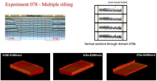 |
| Figure 20. Structures in experiment 078 after 15% extension during second rifting event, illustrated by surface photograph, vertical sections and three cut-out 3-D perspective views. |
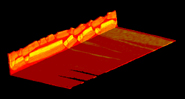 |
Figure 21. Successive horizontal sections through 3-D perspective view at 15% extension during second rifting event (domain 078a; see Fig. 17). Note the absence of a transfer zone in the lowermost part of the model. (Select image to view movie) |
The shape and position of the upper viscous layer had a profound influence on the structural style that developed in the course of the experiment. The upper viscous layer embedded within brittle strata initially caused the development of two independent, decoupled conjugate normal fault systems in upper and lower brittle compartments. The width between conjugate normal faults is related to the depth to the viscous layer. In the part of the model where there was only one basal viscous layer overlain by brittle materials, the width between conjugate faults was large, whereas in that part of the model with a second, upper viscous layer embedded in brittle layers, this width was smaller. In the multiple rifting experiment, the faults that formed during the first rifting event were reactivated and controlled the fault pattern in the overlying brittle layers. The interbedded viscous layer, however, halted upward fault propagation. Conjugate normal faults formed in the upper brittle compartment that were decoupled from the reactivated normal faults in the lower brittle compartment. The location and orientation of extensional transfer zones, visible in horizontal sections and in surface view, was directly linked to the geometry of the interbedded viscous layer. In case the boundary between the interbedded viscous layer and adjacent brittle layers was oblique to the extension direction, vertical transfer zones also formed oblique. In case this boundary was parallel to the extension direction, the transfer zones were also parallel. The experiments suggest that the width between conjugate fault systems and the position and orientation of extensional transfer zones in nature might be directly linked to initial lateral rheological changes within a layered sequence.
Research was funded by the Hochschulstiftung Bern and a grant from the Swiss National Science Foundation (Nr. 2000-055411.98/1).
Byerlee, J.D., 1978. Friction of rocks. Pure Applied Geophysics, 116, 615-626.
Hounsfield, G.N., 1973, Computerized transverse axial scnning (tomography). British Journal of Radiology, 46, 1016-1022.
McClay, K.R. & Ellis, P.g., 1987. Geometries of extensional fault systems in model experiments. Geology, 15, 341-344.
McClay, K.R., Waltham, D.A., Scott, A.D. & Abousetta, A., 1991. Physical and seismic modelling of listric normal fault geometries. Geological Society Special Publication, 56, 231-239.
Stewart, S.A., Harvey, M.J., Otto, S.C. & Weston, P.J., 1996. Influence of salt on fault geometry. Examples from the UK salt basins. In: Alsop, G.I., Blundell, D.J. & Davison, I. (eds.). Salt Tectonics. Geological Society Special Publication, 100, 175-202.
Stewart, S.A., 1999. Geometry of thin-skinned tectonic systems in relation to detachment layer thickness in sedimentary basins. Tectonics, 18, 719-732.
Weijermars, R., 1986. Flow behaviour and physical chemistry of bouncing putties and related polymers in view of tectonic laboratory applications. Tectonophysics, 124, 325-358.