Experiments
The experiments are described in order of decreasing strain rate ratio. The structures in each model are documented by line drawings, surface photographs, CT images and short movies. During deformation of the model a series of vertical sections perpendicular to the longitudinal sidewalls were obtained at regular time intervals using the X-ray technique. At the end of each experiment 135 closely spaced serial cross-sectional CT images were acquired. Plan view photographs of the model were also taken at regular time intervals and document the surface evolution. Visualisation software packages such as NIH Image©, Noesys T3D© and Adobe Photoshop©, were used to digitally enhance CT images, and to compute both horizontal sections and 3D perspective views of the final deformation stage. Surface photographs and enhanced CT images were used to create short movies. These include movies of the surface evolution, movies of the temporal evolution of structures in vertical sections perpendicular to the shear direction, movies of serial 2D cross-sections and 3D perspective views of the final stage of transpression.
Experiment 1661 (strain rate ratio 7.3)
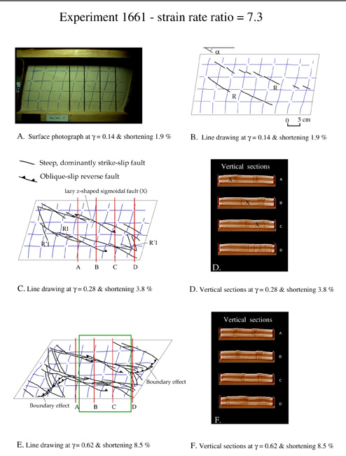
At early stages of deformation two separate zones of en-echelon dextral strike-slip faults form in the brittle layers; (Fig 2A,B; Movies 1661-01, 1661-02) individual fault segments strike at angles between 24° and 30° with respect to the longitudinal borders. The early faults are important kinematic indicators: left-stepping faults in each zone indicate a dextral shear component. Faults are sub-vertical and extend down to the base of the brittle layers. Domains of positive vertical relief are created in areas where two adjacent left-stepping faults overlap. With increasing deformation individual fault segments propagated sideways with different strike orientations and dips. They acquire a slight sigmoidal trace (Z shaped; Fig. 2C) and a small reverse component, whose sense of dip changes along strike: for example, the hanging wall of fault X in section A becomes the footwall in section C (Fig. 2D), a characteristic of so-called scissor faults. With increasing deformation lower-angle dextral faults striking at 15° to 0° (Rl in Fig. 2E, with lower surface strikes than first-formed dextral faults) formed in the overlap area between adjacent left-stepping faults and linked with older faults. This led to an overall fault pattern dominated by major anastomosing dextral strike-slip fault zones. Between these fault zones several sinistral faults striking at high angles of 65° to 70° (R’l in Fig. 2E) developed. These secondary, antithetic faults accommodated only minor displacement and were generally confined between older major dextral fault zones. During increasing deformation, transpression was absorbed on several steeply dipping oblique-slip fault zones with an overall surface strike of about 15°. Movies 1661-03 and 1661-04 show vertical and horizontal serial sections, respectively, through these fault zones. These fault zones are similar to positive flower structures and characteristic of convergent strike-slip fault zone (Movies 1661-05 and 1661-06). The strike-slip component along the oblique-slip faults dominates over the reverse dip-slip component. In plan view dominant offset of faults is dextral, whereas in vertical sections they have a small reverse dip-slip component. Younger lower-angle dextral fault (Rl) branch at depth with older faults. Reverse faults forming at late stages of deformation near the acute borders of the sheared sand pack are boundary effects caused by “scissoring” of the model (Fig. 2E).
 |
| Figure 2. Transpression experiment 1661. (A) Plan view of early stage of transpression. (B,C,E) Line drawings after photographs illustrate fault evolution at three consecutive stages of transpression; fine lines represent coloured sand markers (initially square grids); bold lines represent traces of visible faults. R, in synthetic, dextral strike-slip fault (Riedel shear); R’l lower-angle antithetic fault; Rl, lower-angle synthetic fault. X in (C,D) marks location of scissor fault. Rectangle in (E) indicates area analysed by X-ray computerized tomography (D, F). Vertical sections showing fault evolution at two consecutive stages. Location of sections is indicated by A-D in corresponding line drawings. (Select image for enlargement) |
Experiment 1764 (strain rate ratio 3.6)
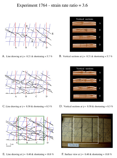
As in the previous experiment dextral strike-slip faults formed early (Fig. 3A,B; Movie 1764-01, 1764-02). The faults are again arranged en-echelon pattern and are left-stepping. However, their surface strike is now more oblique (between 28° and 37)° and reflects the decreasing strain rate ratio. With increasing deformation upward bulging of material occurred between overlapping strike-slip faults and faults obtained a reverse component of slip. Gently-dipping reverse faults, dipping 30-50° (e.g. fault Q in Fig 3C,D), formed in the center of the model between steep dextral convergent fault zones. These faults are interpreted to result from local stress field changes where the maximum compressive stress was reoriented sub-parallel to older strike-slip fault zones. The fact that low-angle reverse faults rather than strike-slip faults developed indicate that the intermediate principal stress axis switched locally from vertical to horizontal.
The lower half of Fig. 3E,F illustrates how strain was partitioned into predominantly pure strike-slip and predominantly pure shortening. Here strike-slip faults strike sub-parallel to gently dipping reverse faults that converge at depth to form a pop-up structure. The strike-slip faults dip steep at the surface and merge at depth with the bounding dominantly reverse faults (Movies 1764-03 and 1764-05). Fault dip can vary considerably along strike. Horizontal sections show the complex fault pattern at depth (Movie 1764-04). The fault zones narrow at depth, where strike-slip faults become sub-parallel to reverse faults.
| Figure 3.
Transpression experiment 1764. (A,C,E) Line drawings after photographs
illustrate fault evolution at three consecutive stages of transpression.
R, synthetic, dextral strike-slip fault (Reidel shear). Faults P,
Q and S are explained in text. (B,D) Vertical sections showing fault
evolution at two consecutive stages. Location of sections is indicated
by A-D in corresponding line drawings. (F) Surface view at final stage
of transpression. Rectangle in (E,F) indicates area analysed by X-ray
computerized tomography. (Select image for enlargement) |
