Experiments (continued)
Experiment 1820 (strain rate ratio 2.7)
Unlike in the previous two experiments, early transpression was taken up by reverse faulting rather than strike-slip faulting (Fig. 4A; Movies 1820-01, 1820-02). Thrust faults dipped at 35-45°, had opposite vergence and bounded a pop-up structure striking parallel to the longitudinal walls. The forward directed thrust predominantly accommodated further deformation and displayed a dextral strike-slip component (Fig. 4B). Dextral strike-slip faults formed within the pop-up structure (Fig. 4C, D). These faults are sub-vertical near the surface, but generally curved at depth and merged with older faults. In front of the pop-up structure a second pop-up structure and steeply dipping strike-slip faults formed. These structures interfered laterally and as a consequence the fault dip varied considerably along strike: from about 30° to sub-vertical (cf. sections B-E in Fig. 4C,D; Movies 1820-03, 1820-04 and 1820-05). Dextral strike-slip faults formed also within the second pop-up structure, striking at 15-25° (Movies 1820-03 and 1820-05). In this area we thus have a partitioning of fault motion between sub-parallel nearly pure strike-slip faults and nearly pure reverse dip-slip faults.
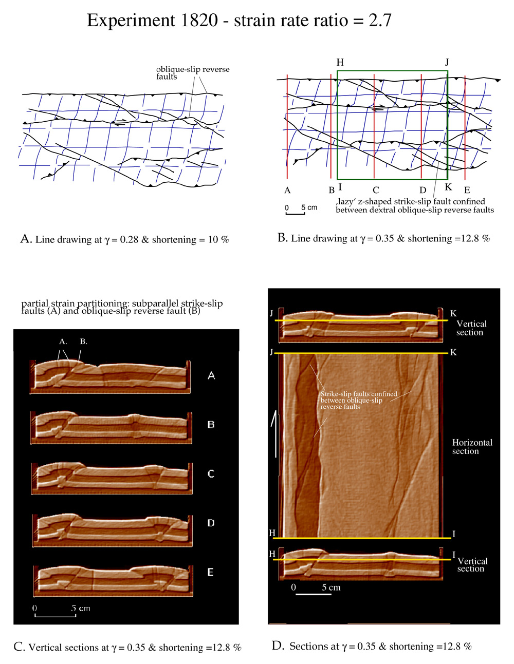 |
| Figure 4. Transpression experiment 1820. (A,B) Line drawings after photographs document structural evolution at two consecutive stages of transpression; Rectangle HIJK indicates area analysed by X-ray computerized tomography. (C) Vertical sections showing fault evolution at final stage of transpression. Location of sections is indicated by A-E in (B), (D) Horizontal section at depth and vertical sections through final stage. (Select image for enlargement) |
Experiment 1770 (strain rate ratio 1.8)
The evolution of this experiment is very similar to that of the previous one. At early stages of transpression a pop-up structure formed striking parallel to the longitudinal walls (Movie 1770-01). The dip of downward converging reverse faults was initially about 35° (Movie 1770-02). With increasing deformation they became dextral oblique-slip reverse faults. A second pop-up formed in front of the older one and also showed a strike-slip component Dextral strike-slip faults (striking at about 25°) formed within the pop-up structures (Movie 1770-02). They have a curved shape in plan view and coalesce with reverse faults (Fig. 4A,B). Some strike-slip faults formed in between pop-up structures (Fig. 5A-C). Vertical sections through the final stage of deformation (Fig. 5D; Movie 1770-03) clearly show the two pop-up structures. Late strike-slip faults within pop-up domains are sub-vertical near the upper surface but curve at depth and merge with oblique-slip reverse faults. In the case where a steep strike-slip fault branches at depth with both forward and backward directed oblique-slip reverse faults of a pop-up structure, its dip direction changes along strike. Horizontal sections reveal a doubly plunging anticline (upper part of fig. 5B; Movie 1770-04): the hinge zone defined by bulging layers in the pop-up domain changed its plunge direction laterally. The structure is partly bounded and partly cut by dextral strike-slip faults, which coalesce with major oblique-slip reverse faults (Movie 1770-05).
 |
| Figure 5. Transpression experiment 1770. (A) Line drawings after photograph illustrating fault pattern at final stage of transpression. Rectangle HIJK indicates area analysed by X-ray computerized tomography. (B,C) Horizontal section at depth and vertical sections through final stage. (D) Vertical sections showing fault evolution. Location of sections in indicated in (A). (Select image for enlargement) |