Elle (Jessell et al. 2001; see title Microdynamics Simulation Bons et al., 2008) is a modelling system with which it is possible to simulate a variety of concurrent microstructural processes that are active at the grain scale during continuous deformation. Individual grains are defined by polygons constituted of nodes and straight boundary segments and form the highest level in the hierarchical polygonal grain boundary structure. Each grain in turn is made up by a number of second-order polygons (subgrains). The lowest level discretization of the microstructure is a Delaunay triangulation (Shewchuk, 1996) of each polygon. A data file stores a complete description of the microstructure at a specific time interval and contains information about geometry, viscosity, strain, stress, dislocation density and age of each individual grain, node and boundary segment. A shell program iteratively combines an ordered set of individual micro-processes which are each described as a distinct code to simulate the effect of a single grain-scale process over a small time increment. The shell program passes the data file from one process to the other. The data file is changed according to the operation of one micro-process.
Editor's note: the original Elle website is no longer accessible - the above is provided as a more recent reference].
In our model we simulate dynamic recrystallization involving viscous simple shear plane strain deformation, crystal lattice rotation, formation of subgrains, rotational recrystallization, recrystallization by nucleation, grain boundary migration and recovery. Driving forces used in our model are dislocation density, grain boundary and surface energy. Theoretical considerations, detailed description and computational explanation of the different microstructural processes simulated are provided in the Appendix A: model description and Piazolo (2001, chapter 3). Simulations model the microstructural development of a quartzite at low grade conditions. Two initial fabrics are used; the fabric is either coarse grained (Movies 1A, 1B and 1C ) or fine grained (Movies 2A, 2B and 2C ). In both cases, the grain size distribution is unimodal. For specific values implemented in the model are given in Appendix B: values.
The simulated microstructures shown in Movies 1A-1C and Movies 2A-2C, closely correspond to microstructures that are commonly attributed to dynamic recrystallization (Figure 1; e.g., Poirier and Nicolas, 1975; Guillopé and Poirier, 1979; Urai et al., 1986; Jessell, 1987; Hirth and Tullis, 1992). During progressive deformation and recrystallization a bimodal grain size distribution develops from the initially coarse grained example (Movie 1A ). This feature is commonly observed in dynamically recrystallized quartzites (Figure 1A, Hirth and Tullis, 1992). A few large, strongly elongated grains that are surrounded by small grains remain even at a strain of 2. Similar to natural examples (Figure 1B) small recrystallized grains develop predominately at the rim of large, old grains and trains of recrystallized grains are seen which crosscut old, large grains ( Figure 1B; Movie 1B )). Additionally, domains of similarly oriented grains are observed (Figure 1C, (Movie 1C )). which compare well to grains that developed during dynamic recrystallization in natural examples (Figure 1C). Microstructures developing from an initially fine grained fabric exhibit a unimodal grain size distribution throughout the deformation experiment (Movie1A). Again, this is often observed in dynamically recrystallized rocks (Figure 1D, Hirth and Tullis, 1992).
Figure 1. Photomicrographs of typical microstructure seen in rocks that have undergone dynamic recrystallization
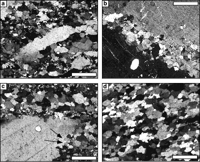
Photomicrographs of typical microstructure seen in rocks that have undergone dynamic recrystallization - scale bars = 0.5 mm; (a) Microstructure characterized by elongate grains with undulatory extinction and recrystallized grains surrounding the large, "old" grains, Qtz-Fsp mylonite, bimodal grain size distribution, Schirmacher Oasis, East Antarctica, crossed nicols. A similar microstructure is seen in Movies 1A-1C (b) Large grain cut by train of small recrystallized grains. Qtz-Fsp mylonite, Schirmacher Oasis, East Antarctica, crossed nicols. A similar feature is seen in (Movies 1A, 1B and 1C ). (c) Tip of a large, elongate, "relict" grain. Recrystallized grains are present at the rim of the large, "old" grain. Grain size of recrystallized grains are in the range of subgrains (arrows). Qtz-Fsp mylonite, Schirmacher Oasis, East Antarctica, crossed nicols. A similar feature is seen in Movies 1A, 1B and 1C . (d) Completely recrystallized quartzite, unimodal grain size distribution, Conceição do Rio Verde, Minas Gerais, Brasil (courtesy of S. ten Grotenhuis), crossed nicols. A similar feature is seen in Movies 2A, 2B and 2C .
Completely recrystallized microstructures were not achieved in any of the experiments, where completely recrystallized means that all grains have gone through at least one stage of either recrystallization by nucleation or recrystallization by lattice rotation of adjacent grains.
In none of the simulations a true steady state microstructure (Means, 1981) developed. This means that the characteristics of the microstructure such as the grain size, orientation of the long axes of grains, or subgrain size still change with ongoing deformation at least up to a finite strain of 2.
Figure 2A. Crystallographic orientation
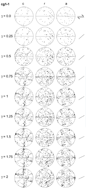
Crystallographic orientation of the c-, r- and a-axes during progressive deformation of the microfabric that was initially coarse grained (cf Movie 1) The shear plane is oriented E-W. For each stage the orientation of the line of maximum finite elongation is shown as a tick mark next to the lower hemisphere equal area projections. With progressive deformation a preferred crystallographic orientation of c-axes with a crossed girdle develops. At high strain clusters of c-axes following a great circle are seen. These are rotated subgrains of large remaining grains. Projections of a-axes show the development of 6 weakly developed maxima that are oriented 60¡ to each other.
Figure 2B. Crystallographic orientation
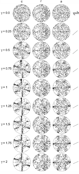
Crystallographic orientation of the c-, r- and a-axes during progressive deformation of the microfabric that was initially fine grained (cf. Movies 2). The shear plane is horizontal. For each stage the orientation of the line of maximum finite elongation is shown as a tick mark next to the lower hemisphere equal area projections. With progressive deformation a preferred crystallographic orientation of c-axes with a crossed girdle develops. There are also 2 noticable maxima at an agble of 40-60¡ to the girdle maxima. Projections of a-axes show the development of 6 weakly developed maxima that are oriented 60¡ to eachother, whereby the two maxima on the horizontal are most pronounced.