Analogue modelling of segregation and ascent of magma
Introduction
Magma is generated by partial melting on the µm to mm-scale in its source rocks and may accumulate and ascend to form > km-scale volumes in the form of batholiths, magma chambers or volcanic outpourings. The whole process involves often over 25 orders of magnitude in scale and deals with a variety of processes on different scales and different levels within the crust or mantle. Time scales also vary over many orders of magnitude, from seconds to hours for hydrofracture propagation involved in ascent of dykes (Emerman & Marrett 1990, Lister & Kerr 1991, Clemens & Mawer 1992) to one or more millions of years for a thermal event that causes partial melting (see discussion in Brown et al. 1995, Petford et al. 2000). The sheer range of scales involved inhibits any numerical or experimental modelling of the whole process. This has limited most modelling to only one aspect or one step of the whole process.
On the smallest scale, melting experiments have been done on real rocks (van der Molen & Paterson 1979, Dell'Angelo & Tullis 1988, Rushmer 1995) and on analogue materials (Means & Park 1994, Park & Means 1996, Grujic & Mancktelow 1998, Rosenberg & Handy 2000). Ascent by dyking has been extensively modelled numerically (Weertman 1971, Spence & Turcotte 1985, Lister & Kerr 1991, Petford et al. 1993, Rubin 1995a; 1998, MŽriaux & Jaupart 1998, Dahm 2000) and with analogue models using gels (Maal¿e 1987, Takada 1990, Lister & Kerr 1991, Dahm 2000). Diapirism has been modelled for decades, most famously by Ramberg (1967), and more recently by, for example, Whitehead & Helfrich (1990) and Anma & Sokoutis (1997).
A limitation to most of these models is that they do not provide much insight into how one step links to the next. For example, numerical models on dyke ascent usually assume a certain influx or pressure at the base of a dyke (e.g. Lister & Kerr 1991, Rubin 1993, MŽriaux & Jaupart 1998). Similarly, analogue models for dyking use a certain flux of the magma analogue (e.g. air, water) from an outlet to start a "dyke". Such models assume that influx or pressure is sufficient and can apparently be maintained to make the model work. Such models normally do not explain how the previous step in the sequence links with the one under consideration (Weinberg 1999). It appears as if it is tacitly assumed that each step does not influence the next step.
Here we present movies of analogue experiments of melt segregation and magma ascent. Although the experiments are physically restricted to model only a certain scale, we argue that they represent steps in a stepwise process of segregation and ascent on an ever increasing scale. The movies should thus be envisaged as "snap shots" taken along the road that a magma may take from initial formation to ascent as dykes. The basic ideas presented in this paper were published by Bons and van Milligen (2001) and Bons et al. (2001), illustrated with still-images from some of the movies that are presented in this paper. The main aspect of this paper is to show movies of these experiments, which are more informative than the images shown in the aforementioned papers.
Analogue experiments of stromatic migmatites
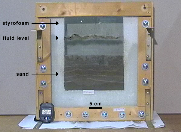
To simulate melt segregation in partial melts, we used a simple mixture of sand, sugar water and bakers' yeast. Fermentation of sugar by yeast produces ethanol and CO2 gas. The gas, being bouyant, is the analogue of melt. The experiments were done in a semi-2 dimensional glass tank (40 x 40 x 1.5 cm) (Fig. 1). The glass tank was filmed with a digital video camera (756x512 pixels, 25 frames/s).
|
Figure 1. Glass tank that was used for the segregation experiments. The simple set-up consists of a wooden frame that holds together two glass plates that are separated by styrofoam, to create a 1.5 cm wide sample chamber. Ascent experiments were carried out in a similar, but larger tank.
|
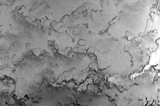
Initial fluid-filled porosity was about 25%. Fermentation produced gas at a steady rate of about 5·10-3 %/s. The gas partly replaced the pore fluid and after about two to three hours the total porosity settled at around 40%, half of which was gas-filled. Figure 2 shows the highly dynamic evolution of the system over a two hour period. Gas accumulates in horizontal hydrofractures to form a structure similar to a stromatic migmatite. Hydrofractures, fractures that are propped open by the internal fluid pressure (Hubbert & Willis 1957, Secor 1965), are also thought to occur in otherwise ductile partial melts, owing to high melt pressure induced embrittlement (Nicolas & Jackson 1982, Sleep 1988). The hydrofractures do not grow and link to create a percolating network through which the gas can steadily escape the sample, as envisaged by, for example, Nicolas (1986). Instead, hydrofractures grow slowly and coalesce or drain into others in sudden events (Fig. 3) in between periods of quiescence.
|
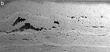
Figure 2. Movies of the growth and collapse of gas-filled hydrofractures. (a) second hour of the experiment. (b) Third hour of the experiment. Time between frames is 1 minute. Width of view is 21 cm.
|
|
|
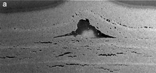
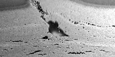
Figure 3. Movie of the collapse of a large laccolithic hydrofracture, which grew over a period of about half an hour and collapsed within less than a second. The collapse produces a thrust fault, with some remaining air pockets, although their is no bulk horizontal shortening of the sample. Movie length in real time is 4 s, with frames 0.04 s/frame. Width of view is 16 cm.
|
|
Sharp straight fractures are typical for the first day of the experiment. After about a day, the gas accumulates in bubbles and irregularly shaped hydrofractures fractures (not shown here). We do not know the reason for this change in geometry, but the behaviour of stepwise ascent and accumulation remains unchanged (Bons & van Milligen 2001).
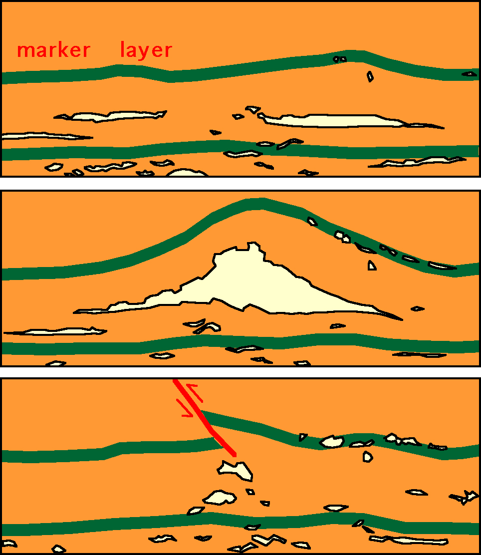
At any time it is difficult to tell from the current structure where large hydrofractures once resided. The deformation caused by the formation of a hydrofracture is usually largely reversed upon collapse and drainage. Figure 3 and 4 shows an interesting exception to this. Opening of a very large laccolithic hydrofracture causes stretching of the overlying layers. Collapse of the hydrofracture necessitates shortening of these layers, which occurs by a thrust fault. Some gas remains trapped along the thrust. Similar structures of leucosomes along reverse faults or axial planes of folds are frequently found in migmatites (e.g. fig 9b in McLellan 1988, fig. 1e in Brown et al. 1995). The experiments show that these may result from collapse and escape of melt volumes. It should be clear that the formation of the laccolith is an effect of the experimental boundary conditions (free upper surface). However, effects similar to those caused by the experimental laccolith can be expected in migmatites (formation and collapse of a large melt volume), although the geometry would not resemble a laccolith.
|
Figure 4. Drawings of three stages of the collapse of a large laccolithic hydrofracture (Fig. 3a) to show the formation of a thrust structure in a marker horizon due to collapse of the hydrofracture. Notice that there is no overall horizontal shortening of the sample. |
Wet sand is a Mohr-Coulomb type material. The observed segregation and accumulation behaviour is, however, not restricted to this mechanical behaviour of the solid matrix. Similar experiments in stiff gelatine (purely elastic-brittle) with sugar and yeast yielded similar results (Figure 5). This shows that the actual mechanical behaviour of wet-sand or gelatine is not a controlling factor in the stepwise accumulation of hydrofractures.
| Figure 5. Segregation of gas from fermenting sweet gelatine in a glass jar. Contrary to the Mohr-Coulomb wet sand, gelatine is purely elastic-brittle. Gas accumulates in irregular hydrofractures that occasionally collapse and expel their gas content. Fractures are irregular in shape. A main fracture is horizontal about one-fifth from the bottom of the picture. It inflates slowly and then drains towards the right (side of jar) several times. One frame per minute. Width of view is 3.6 cm. |