Modelling
Hydrodynamic model
For the numerical simulation of spiral development, we use the 3D hydrodynamic model described in detail by Masuda & Ando (1988) and Masuda & Mochizuki (1989). The porphyroblast and matrix are modelled numerically as a rigid sphere embedded in a Newtonian viscous fluid. The sphere volume increases at a constant rate, and growth is assumed to involve volume-for-volume replacement of the fluid matrix. Deformation of the matrix is by simple shear far from the sphere, and when coupled to the matrix, the sphere rotates at a rate equal to half the far field simple shear strain rate. Porphyroblast rotation in the numerical simulations is described relative to the simulation boundaries. The velocity vector is continuous and equal to zero at the interface between the sphere and matrix, and there is no slip at the interface. Marker particles are set in the matrix to represent the foliation, and these move passively as the matrix deforms, while those included in the growing sphere rotate as the sphere rotates. We first conducted simulations to represent both the rotation and non-rotation models of spiral development (see below for simulation descriptions). For these simulations, the initial radius of the sphere was set at 0.1, and the increase in sphere volume per unit time was 0.001. The far field strain rate was 0.002 per unit time, and both sets of simulations were run until a far field shear strain value (gamma) of 8. Additional simulations were run to test the effect of changing the values of such variables as sphere growth rate on the resulting 3D spiral geometry, and the conditions of these simulations are described at the relevant parts of the text.
Description of rotation and non-rotation simulations
The rotation simulation involved foliation-parallel simple shear deformation, and this results in shear-driven rotation of the sphere (Fig. 1a). The non-rotation simulation involved simple shear deformation and the development of four overprinting orthogonal foliations, without rotation of the sphere. The change to each new foliation was modelled by rotating the shear plane 90 degrees, while ensuring that shear sense was kept constant (i.e. consistently clock-wise or anti-clockwise) during the course of the simulation. The timing of each new foliation was decided at the stage where the currently deforming matrix foliation, adjacent to the sphere, had developed approximately 90 degrees rotation relative to the sphere (Fig. 1b). The non-rotation model, as described by Bell (1985) and Johnson (1993b), involves partitioning of matrix deformation into zones of coaxial shortening close to porphyroblasts, and zones of non-coaxial strain that anastomose around the porphyroblasts. Such a pattern of strain partitioning is too complex to model numerically, so we modelled matrix deformation under conditions of simple shear. We consider this to be an adequate approximation for the following reason. In the non-rotation model, inclusion trail curvature, and ultimately spiral-shaped inclusion trails, originate from crenulation of the matrix foliation in zones of non-coaxial strain (cleavage seams of a developing crenulation cleavage) adjacent to the growing porphyroblast. The curved (crenulated) foliation is later included within the porphyroblast as it grows toward, and eventually over the adjacent cleavage seam. Thus, although Bell (1985) describes the porphyroblast as occupying a zone of coaxial strain, for the purposes of our numerical simulation it is more appropriate to deform the matrix by non-coaxial shear. Given this pattern of non-coaxial deformation, the non-rotation simulation should theoretically result in sphere rotation. In order to solve this inconsistency, we imposed a condition of non-rotation upon the sphere (parameter k of Bjornerud & Zhang, 1994), and removed the spin-related part of the velocity field (the total velocity field is calculated from two components: the matrix velocity vector and the component of shear due to effect of rotation of sphere on surrounding matrix). This does not affect the validity of the physics of matrix fluid flow (and particle movement) around the non-rotating sphere. The suitability of our simulation as an approximation of Bell’s (1985) non-rotation model can be assessed from Figure 2, which compares the velocity vector pattern from our non-rotation simulation with Bell’s deformation partitioning model. The simulation approximates a single microlithon of Bell’s model. The proposed area of coaxial strain adjacent to the porphyroblast (light grey area in Fig. 2a) is approximated in the simulation by an area of low flow velocity (light grey area in Fig. 2b), which although not coaxial, is a zone of minimal particle flow.
The numerical modelling described above involves limitations and assumptions resulting from the necessary numerical simplification of a complex natural system. The heterogeneous rock matrix is modelled as a homogeneous fluid, and the porphyroblast as a perfect sphere. Important strain accommodation such as crenulation development, recrystallisation, and grain-scale deformation processes are not simulated. In the non-rotation simulation, we impose a condition of non-rotation upon the sphere, although under the physical conditions of the simulation the sphere should rotate. These kinds of limitations are common to previous studies of spiral development (Masuda & Mochizuki, 1989; Bjornerud & Zhang, 1994; Gray & Busa, 1994), but do not preclude the geologic relevance and value of such an investigation. Thus, the modelling provides a useful and instructive approximation of the end-member models, and provides an advance of our interpretation of these controversial microstructures.
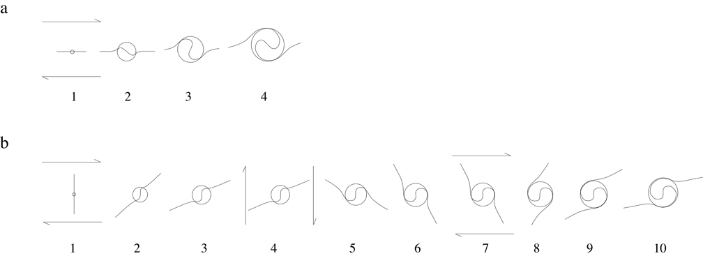
Figure 1. Schematic description of the rotation and non-rotation simulations used in this study

(a) Rotation simulation. The matrix is deformed by foliation-parallel simple shear, and the growing sphere is fully coupled to the surrounding matrix. (b) Non-rotation simulation. The irrotational sphere grows during the development of four overprinting orthogonal foliations. New foliations are initiated at stages 1, 4 and 7. Note: The division of each simulation into numbered stages indicates progressive development of the spiral, and the divisions don’t represent equal intervals of time or deformation.
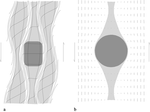
Figure 2. Comparison of non-rotation simulation with the non-rotation model as described by Bell (1985)
(a) Strain partitioning model of Bell (1985). The porphyroblast (dark grey) lies within a field of coaxial strain (light grey) and thus does not rotate with respect to shear plane. Strain is partitioned into zones of shear (white) that are represented by cleavage seams in real rocks. The outer microlithons do not house porphyroblasts, and thus strain within these areas is non-coaxial. (b) Velocity vector field of the non-rotation simulation used in this study. The lengths of the bars indicate the relative magnitude of flow velocity, and the orientation indicates flow direction. The spherical porphyroblast (dark grey) is surrounded by an area of low matrix velocity (light grey), although this zone is non-coaxial (cf. Fig. 1a). The areas of higher matrix velocity (white areas) undergo strongly non-coaxial shear, which corresponds to the white areas in Fig. 1a. The simulation represents the central microlithon, porphyroblast and adjacent zones of shear as shown in (a).