Classification of refold structures
The complex geometries resulting from superposition of folding have been classified by characteristic fold interference patterns, which appear on two-dimensional sections through the three-dimensional refold structures (Ramsay, 1967, 1987, Thiessen and Means, 1980, Thiessen, 1986). Ramsay (1967) presented a classification of refold structures, which combines two-dimensional interference patterns and three-dimensional superposition geometries, suggesting that individual patterns are indicative for specific spatial angular relationships between the two folding events. These classes (Type 0 - 3) are distinguished by whether the initial fold axes and/or the initial fold axial planes are deformed during the superposed generation of folding (Fig. 1). The angle between the first (f1) and second fold axis (b2) is called a whereas b is the angle between the pole to the first axial plane (c1) and the second slip or transport direction of heterogeneous displacement (a2).
Figure 1. Description of kinematic axes of the initial and superposing fold and their relative spatial orientation
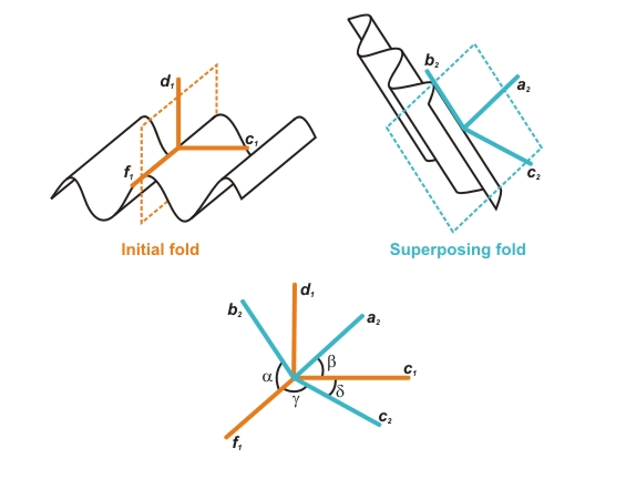
Description of kinematic axes of the initial and superposing fold and their relative spatial orientation (after Ramsay, 1967 and Thiessen and Means, 1980). Initial fold: fold axes = f1; normal to axial plane = c1; direction of heterogeneous shear displacement = d1. Superposing fold: fold axes = b2; normal to axial plane = c2; direction of heterogeneous shear displacement = a2. Angles between f1 and b2 = a; between c1 and a2 = b; between f1 and c2 = g; between c1 and c2 = d.
Using a kinematic modelling computer program Thiessen and Means (1980) introduced g, which is the angle between f1 and the pole to the second axial plane (c2), d1, which represent the normal to a plane containing c1 and f1, and d, which is the angle between c1 and c2. Various orientations of axes of the first (f1, d1, c1) relative to axes of the second fold (b2, a2, c2) can be represented by points in a cubic volume with a, b and g plotted along its edges. Because the angles are not independent, not all combinations of a, b and g are possible. Based on this orientation volume diagram and following the terminology of Ramsay (1967), Thiessen and Means (1980) concluded that b and g are appropriate angles for refold classification but that only few interference patterns are really diagnostic for superposition geometries. A single interference pattern can be produced by an infinite number of refold geometries. Furthermore, they concluded that Type 0 refolds do not create in a strict sense interference patterns and that two different geometries of Type 0 refolds exist.
The terminology used in the presented study follows the terminology of Ramsay (1967), which is well established in structural geology textbooks, and extends the ideas of Thiessen and Means (1980) in following points: (i) The terminology "Type 0-3" is used for end members of three-dimensional refold geometries and not for two-dimensional interference patterns, which have a larger variability (compare fig. 10 in Thiessen, 1986). (ii) Type 0 refolds are further subdivided in three geometrically individual end-members. Because these classes can be simply derived from the refolds Type 1-3 by rotation of the second fold by 90° around the b2 axis, Type 0 is subdivided in Type 01, Type 02 and Type 03. Directions f1, d1, c1 of the initial fold and b2, a2, c2 of the superposing fold are called in the following (orthogonal) kinematic axes of the folds (Fig. 1).
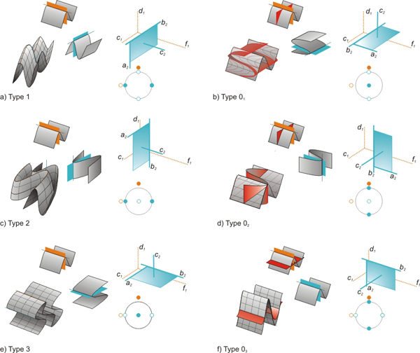
Figure 2. Classification of refold structures
Classification of refold structures showing a) Type 1, b) Type 01, c) Type 2, d) Type 02, e) Type 3 and f) Type 03. and corresponding (i) physical orientation of the first and the second fold generation; (ii) resulting, idealized three-dimensional refold structure (iii) orientation of the kinematic axes of the initial and the superposing fold and (iv) stereographic projection of the orientation of the kinematic axes of the initial and the superposing fold (refold-stereoplot).
Figure 2 shows the suggested new classification plotting for each end-member type: (i) The orientation of the first and the second fold generation; (ii) The idealized resulting three-dimensional refold structure; (iii) The orientation of the orthogonal kinematic axes of the first and the second fold generation; (iv) A stereographic projection of the orientation of the kinematic axes of the first and the second fold generation. Concluding, the following six end-member refold types, with an angular relationship of the initial and superposing kinematic axes of either 0° or 90° can be distinguished:
Type 1 refold (a and b = 90°, g = 0°, Fig. 2a): The initial axial plane remains planar, but the fold axes of the superposed fold are deformed. This causes a strong undulation of the hinges of the initial folds resulting in culmination domes and depression basins, where each depression is surrounded by four culminations and each culmination is surrounded by four depressions resembling the shape of an egg-carton. Two-dimensional sections through the refold structures are often characterized by dome and basin interference patterns (Thiessen, 1986). If a < 90° the domes and basins are arranged en echelon (O'Driscoll, 1962).
Type 2 refold (a = 90°, b and g = 0°, Fig. 2c): The initial axial plane and the initial fold axis are deformed. If the refold structure is progressively unroofed perpendicular to b2,interference patterns with circular forms, rounded triangulars, crescent shapes and typical dome-crescent-mushroom patterns characterize the sections (Ramsay and Huber, 1987). However, oblique sections, especially if the refold structures deviate from the end-member orientation, show a great variability of complex interference patterns (Thiessen, 1986).
Type 3 refold (g = 90°, a, b = 0°, Fig. 2e): The initial axial plane is deformed but the initial fold hinges are not bent by superposing folding. Cross sections parallel to the fold axes (f1 and b2) will not develop a complex interference pattern but show parallel, straight lines. However, cross sections normal to the fold axes will show complex convergent-divergent or hook shaped interference patterns (Thiessen, 1986).
Type 0 refold structures always develop when b and g = 90°. On two-dimensional sections through the refold structures no characteristic interference pattern is developed resembling a cross section through a single-phase fold. Although two different end-member geometries of Type 0 refolds have already been noted by Thiessen and Means (1980), these type of refold structures have attracted little attention of structural geologists mainly because their differences would be difficult to observe in the field. However, if the initial fold generation is cut by a marker plane (e.g. a dyke or vein) at a high angle to f1, differences become obvious and three classes have to be distinguished. Note that additionally d, the angle between the normals to the axial planes (c1 and c2), is needed for this discrimination (Table 1):
Table 1. Angles between the kinematic axis of the initial and the superposing fold and the corresponding end-members
| f1|b2 | c1|a2 | f1|c2 | c1|c2 | |
|---|---|---|---|---|
| Type 1 | 90° | 90° | 0° | 90° |
| Type 01 | 90° | 90° | 90° | 90° |
| Type2 | 90° | 0° | 0° | 90° |
| Type 02 | 90° | 90° | 90° | 0° |
| Type 3 | 0° | 0° | 90° | 90° |
| Type 03 | 0° | 90° | 90° | 0° |
Type 01 refold (a, b, g, d = 90°, Fig. 2b): The shearing direction of the superposing fold is parallel to f1 but axial planes c1 and c2 are perpendicular to each other. The resulting refold structure is identical to the shape of the initial fold. However, a planar passive marker normal to f1 clearly demonstrates the superposition of heterogeneous deformation. Although cross sections normal to f1 shows a simple section through a cylindrical fold the deformation is markedly non-plane strain. By rotation of the superposing fold around b1, end-member structures Type 1 and Type 01 can be continuously transformed into each other (Fig. 4a and b).
Type 02 refold (a, b, g = 90°, d = 0°, Fig. 2d): The shearing direction of the superposing fold is parallel to f1 and the axial planes c1 and c2 are parallel to each other. The resulting refold structure is again identical to the shape of the initial fold but a planar passive marker normal to f1 reveals the superposition of heterogeneous deformation. Again the deformation in a two-dimensional section normal to f1 is markedly non-plane strain. By rotation of the superposing fold around b2, end-member structures Type 2 and Type 02 can be continuously transformed into each other (Fig. 5a and b).
Type 03 refold (b, g = 90°, a, d = 0°, Fig. 2f): Axial planes and fold axes of the initial and the superposing fold are parallel to each other. However, the resulting refold structure is not identical in shape of the first fold but may be amplified, overprinted or theoretically cancelled. In case of out-of-phase relationship of the waveform of the superposing fold, generation of second order folds on the first fold generation may occur (polyharmonic folds). However, the deformation in a section normal to f1 is plane strain. This Type 03 refold structure correspond to the Type 0 redundant superposition (Ramsay, 1967; Thiessen and Means, 1980; Ramsay and Huber, 1987). By rotation of the superposing fold around b2, end-member structures Type 3 and Type 03 can be continuously transformed into each other (Fig. 6a and b).