Animation of refold structures
Animation of refold structures
The animations show finite refold geometries of two folding phases having the same wavelength/amplitude ratio of 2. Two kinds of movies are presented: three-dimensional surface plots (referred to as structure-movies), and fold interference patterns on three perpendicular faces of a block oriented perpendicular to the kinematic axes of the initial fold (referred to as pattern-movies). The animations show the geometrical transition from one refold end-member into another - in 18 steps, with 5° difference each. Note that the orientation of the block models does not change and is identical through all animations. Therefore changes in the shape of the interference patterns result from different superposition geometries and not from changing section orientations. The layers shown in the structure-movies consist of a central layer (dark yellow), visualizing the refold structures, and blue and/or red orthogonal marker layers that were introduced as planes after the first folding event. These marker layers visualize the orientation of the second fold and are therefore crucial for recognizing and distinguishing (!) Type 01, 02 and 03 refolds. In the pattern-movies refolded marker layers creating interference patterns are shown in dark yellow and pink. Orthogonal marker layers are shown in blue.
Figure 3. Refold-stereoplot
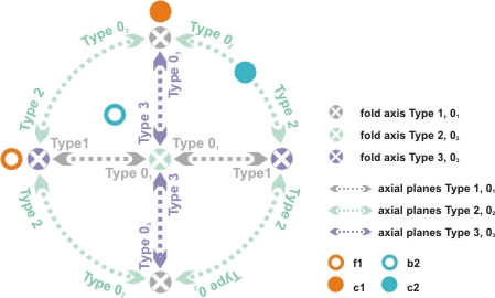
Refold-stereoplot with a fixed orientation of the initial fold having a horizontal W-E striking fold axis and a vertical axial plane with a horizontal pole striking N-S. The c2 axes of two different types of end-member refolds plot in the N-S (Type 02 and 03), W-E (Type 1 and 2) and central position (Type 3 and 01) of the refold-stereoplot.
Both the structure- and the pattern-movies additionally show an animated stereographic projection (referred to as refold-stereoplot) of the incremental orientation of the fold axes and axial planes of the initial and superposing fold (Fig. 3). In this refold-stereoplot the spatial orientation of the initial fold is always fixed: f1 is oriented horizontally W-E and the axial plane is vertical striking W-E with a pole c1 oriented horizontally N-S. Because the refold Types 1-3 can be transformed in their Types 01-03 counterparts by simply rotating their axial plane around the superposing fold axis b2 this transformation between the end-member positions can be elegantly displayed by traces of c2 during rotation along either the periphery or along the N-S and W-E diameter of the refold-stereoplot (strictly speaking traces of c2 during rotation plot along small circles around b2 for any spatial orientation of the superposing fold):
(i) Type 1 refolds plot in the periphery (fold axis N and S, c2 E and W) and are transformed to Type 01 refolds by translating c2 along the W-E diameter towards the centre of the refold-stereoplot. (ii) Type 2 fold axes plot in the centre of the diagram, c2 in the E and W. The refolds are transformed to Type 02 refolds by moving c2 along the periphery of the refold-stereoplot in a N-S orientation. (iii) Type 3 fold axes plot in the E and W, c2 plots in the centre of the diagram. The refolds are transformed into Type 03 refolds by translating c2 along the N-S diameter towards the periphery of the refold-stereoplot.
Note that although always two different end-member refolds are plotting at the same N-S, W-E or centre node of the refold-stereoplot, the structures are clearly distinguished by the orientation of their fold axis b2. The following section gives a short description of the structure- and pattern-movies of all 15 possible combinations of the 6 end-member structures. Although such progressive transitions between the end-member types are purely geometrical we think that a careful study of these animations of developing refold shapes together with the wide range of possible interference patterns is a perfect training for the understanding of complex three-dimensional shapes and intersections occurring in nature. The movies are described in following logical groups:
The geometrical difference between the end-members requires rotating c2 around b2 by an angle of 90Á. Consequently the superposing fold axis does not change its orientation. A natural example of such transitions could be expected in polyphase deformed areas with a great variability in the orientations of the axial plane and a uniform distribution of the fold axis of the superposing folds (e.g. Fusseis, 2001). Note that, despite Type 01 - 03 do not produce any visible interference patterns, irregular interference patterns can be observed along most of the transition paths. Structures between Type 1 and 01 will be characterized by dome-basin and/or pronounced banded s-z-shaped interference patterns, almost resembling an asymmetric crenulation cleavage with microlithons and cleavage domains (e.g. Passchier and Trouw, 1996). These banded s-z-shaped structures are typical and frequently found on two-dimensional sections in polyphase folded areas (Ramsay and Lisle, 2000). Such banded structures also occur on sections through structures between Type 2 and 02, where additionally crescent and w/m-shaped intersections are found. Interferences on sections normal to the fold axes from structures between Type 3 and 03 are dominated by all variations of hooks and irregular convergent-divergent patterns. Note that this progressive transition between Type 3 and 03 is the only model, where sections parallel to the fold axes would always record plane strain deformation.
These animations show the transitions between the classical end-members of fold interferences (Ramsay, 1967). Shapes like convergent-divergent hooks, dome and basins and dome-crescent-mushrooms patterns can be observed in the movies. However, note the great complexity and variety of the patterns even on sections orthogonal to the kinematic axes of the perfect cylindrical initial folds. Type 1 is transformed in Type 2 by rotation parallel to c2 and therefore the superposing axial plane does not change its orientation. Similarly the transition from the Type 2 into Type 3 requires a simple rotation around the orientation of c1.
Whereas all previous examples could be transformed by a single rotation about one of the kinematic axes of the superposing fold, the transition of Type 1 into Type 3 needs either two kinematic rotation axes, or a single, oblique rotation axis that has to be constructed from the refold-stereoplot: (i) Find the great circle containing b2 of both Type 1 and Type 3 refolds and determine its pole Pb2. (ii) Find the bisector of the angle between b2 of Type 1 and b2 of Type 3 refold. (iii) Draw a great circle between the bisector and Pb2 (iv) Repeat this construction for c2 of both Type 1 and Type 3 refolds. (v) The intersections between the great circles containing the bisectors represents the single oblique rotation axis transforming Type 1 into Type 3 refold structure.
This set of animations show the transition between Type 0 refold structures and emphasizes the importance of distinguishing between the suggested classes Type 01, 02 and 03.
The transformations from Type 01 into 02 and Type 02 into 03 are again controlled by a simple rotation around one of the kinematic axes of the superposing fold (a2 and c2 respectively). On sections perpendicular to f1 no interference patterns are observed, and the sections normal to d1 and c2 show simple linear intersections throughout the transformation. However, folding of a marker layer intruded normal to f1 and/or to d1 clearly demonstrates the superposed heterogeneous deformation. If this superposition is not recognized, the assumption of plane strain in a cross section perpendicular to f1 is wrong and could lead to potential misinterpretations (e.g. when reconstructing balanced cross sections).
The transformation from Type into 01 into 03 is more complex and was performed using two rotations around a2 and c2. A single oblique rotation axes can be constructed from the refold-stereoplot with the same method outlined above. Although both end-members show no interference patterns on orthogonal sections to the kinematic axes of the initial fold, the transition refolds create a broad spectrum of complex interference shapes, e.g. dome-basins, crescent, s/z, complex hooks and banded structures.
The remaining six transformations between end-members describe transitions from Type 1, 2 and 3 refolds to Type 0 classes excluding the simple rotations around b2 already described. The Type 1 into Type 03 transformation results from a single rotation around the a2 axis. On a section perpendicular to this rotation axis regular dome-basin interference patterns (egg-carton structures) are progressively converted in en-echelon basin and domes (OÍDriscoll, 1962) until all refolds are cylindrical with parallel fold axes resulting in linear intersection on planes perpendicular to d1 and c1 respectively. The Type 3 into Type 01 transformation is again based on a single rotation but contrary to the previous example around the c2 axis. On sections perpendicular to the f1 axis hooks are progressively "unfolded" and similar to the previous model result in cylindrical refolds with parallel fold axes and consequently in linear intersections on planes perpendicular to d1 and c1.
The following transformations are more complex and require rotations of the superposing folds around oblique axis or again, as they were modelled for the movies shown, around two, orthogonal axes:
The transition from Type 1 into Type 02 shows on the section normal to d1 changeovers from dome-basins into asymmetric mushroom shapes and banded s/z structures. Interference patterns on sections normal to c1 reveal an interesting succession from unfolding, asymmetric folding and again unfolding to linear intersection. The symmetric fold intersections on the section normal to f1 transform into dome-basins, which get progressively overprinted with hooks showing again symmetric folds after complete transformation into Type 02 refolds.
The interference patterns on three sections perpendicular to the kinematic axes of the initial fold between the end-members Type 2 and Type 01 are characterized by symmetric crescent mushrooms shapes normal to d1, hooks normal to f1 and banded s/z and w/m shapes normal to c1.
Whereas the interference patterns on two orthogonal sections of the transformation model between Type 2 and Type 03 are very similar to patterns discussed in the previous two models, showing asymmetric mushroom shapes and banded s/z structures, the section perpendicular to f1 is striking complicated: banded structures reveal multifaceted changes in irregular hook shaped folds.
The transformation of Type 3 into Type 02 creates rather similar interference patterns than Type 3 into Type 01 or Type 03: Hook-shapes of the convergent divergent patterns on sections normal to f1 are progressively "unfolded" resulting in a sinusoidal intersections in the Type 0 end-members, but on other orthogonal sections only straight intersections can be observed. However, careful inspections of the movies reveal the distinct differences emphasizing the need to distinguish between Type 01, 02 and 03. Even more important is the fact that only the transition into the Type 03 end-member is plane strain and all other sections normal to f1 are markedly non-plane strain.
Given the striking complexity of interference patterns and their continuous transitions between the end-member refold structures, this short description of the movies is far from being complete. It is left to the reader to explore the great variability of interference patterns and to compare the results of the animations with shapes suggested by Thiessen (1986). It is very instructive to observe the development of the blue and red marker planes introduced to the models after the initial folding especially when Type 0 end-members are modelled. Without this marker planes it is impossible to distinguish between Type 01, 02 and 03.