Experiments with different ratios of brittle to viscous layer thickness (and therefore strength) have been executed. The results demonstrate that with increasing brittle strength to viscous strength ratio (BS/VS), deformation becomes more localised with fewer faults absorbing more deformation. In other words, the fault density decreases with increasing BS/VS ratio. This can be observed in Figure 4, where the resulting strain patterns and interpretations of 9 experiments have been plotted (some of the physical properties for the experiments are given in Table I and 2). Furthermore, the surface extent of deformation inside the box decreases with increasing brittle strength to buoyancy force ratio (BS/BF) (Figure 5). For all the experiments, the extent of the deformed area rapidly increases in magnitude in the first 10-30° of rotation and then slows down until it stagnates (except for experiment 1) (Figure 5). For relatively high BS/VS ratios, the rapid increase takes place in the first ~ 10° (experiments 5, 7 and 8), while for relatively low BS/VS ratios, this occurs in the first ~ 30° (experiments 1, 2, 3, 6 and 9).
Figure 4a, 4b, and 4c. Photographs and interpretation of experiments
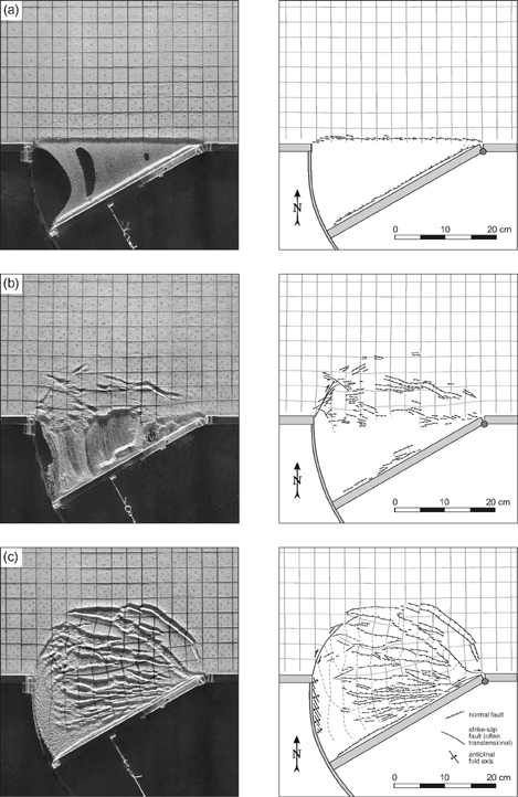
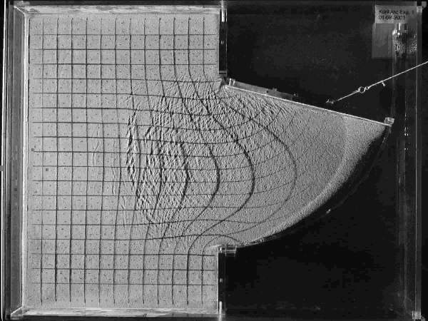
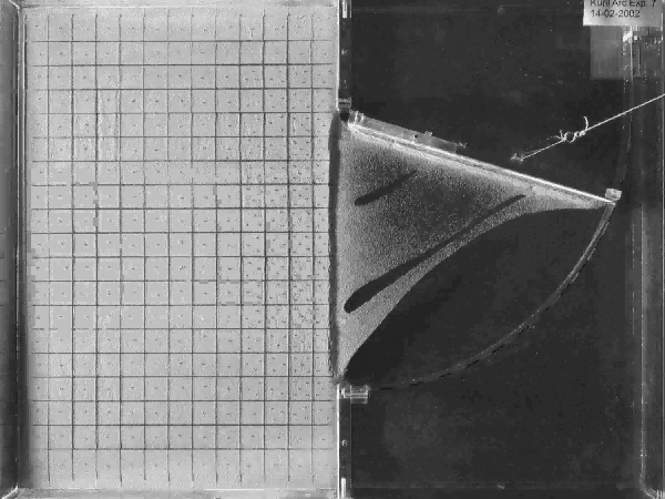
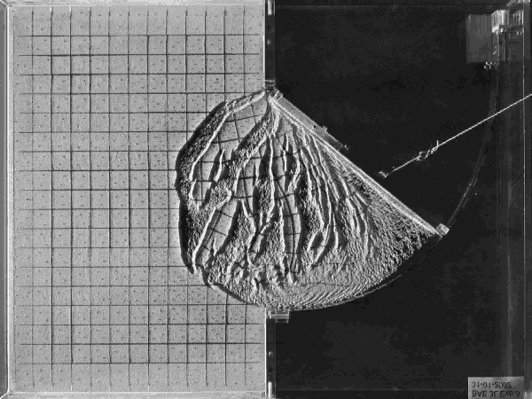
Photographs (left) and interpretation (right) of experiments with different styles of extension for different ratios of brittle strength versus viscous strength (BS/VS) and different buoyancy force of the lithosphere. (a) BS/VS > 25 (exp. 7), (b) BS/VS ~ 25 (exp. 5), (c) BS/VS ~ 18 (exp. 8). All of the images are after 30° of rotation.
Figure 4d, 4e and 4f. (continued)
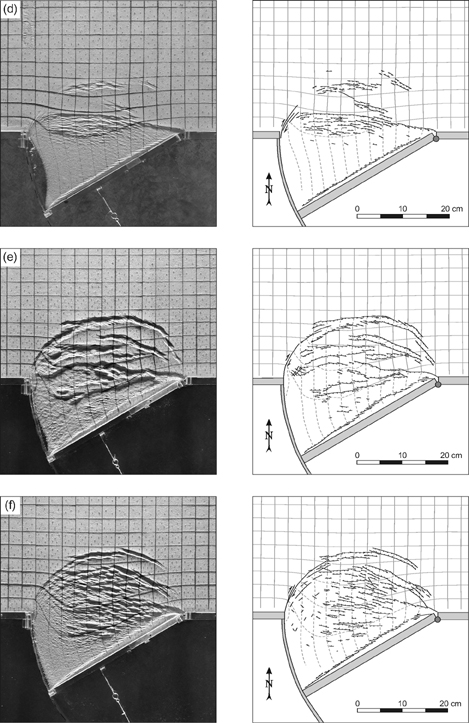
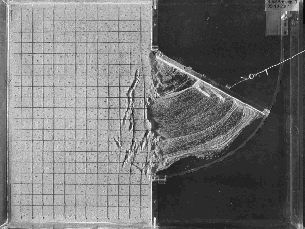
(d) BS/VS ~ 16 (exp. 9) (e) BS/VS ~ 12.5 (exp.4) and (f) BS/VS ~ 8.3 (exp. 3).
Figure 4g, 4h and 4i. (continued)
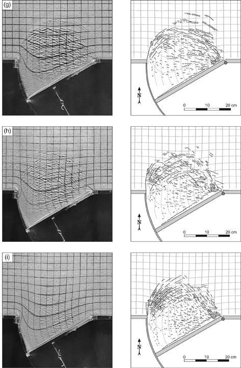
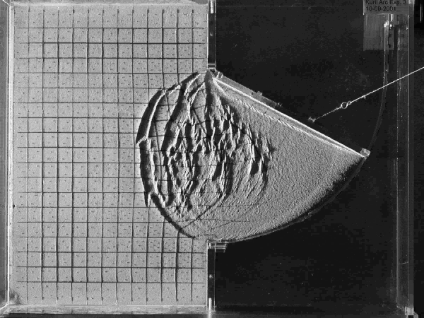
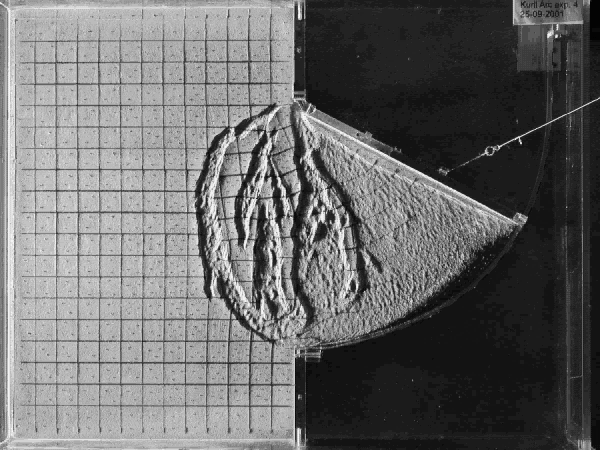
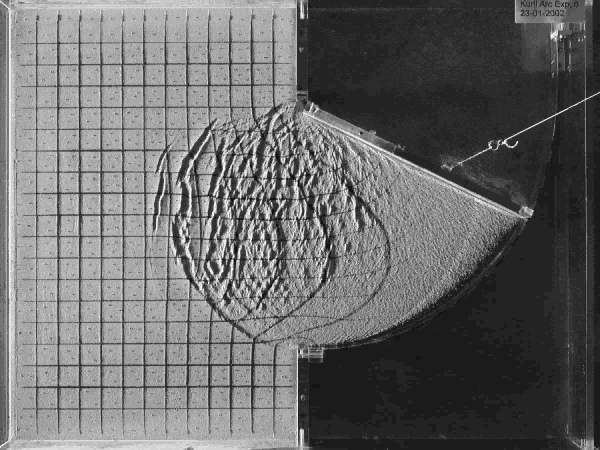
(g) BS/VS ~ 6, (exp. 6), (h) BS/VS ~ 4 (exp. 2) and (i) BS/VS ~ 2.4 (exp. 1).
Table 2. Experimental ratios for different experiments
| Experiment | Layer thickness ratio (B/V) | BS/VS (N/m / N/m) | Buoyancy Force (N/m) | BS/BF | IS/BF |
|---|---|---|---|---|---|
|
B = brittle, V = viscous, BS = brittle integrated strength, VS = viscous integrated strength, IS = total integrated strength, BF = buoyancy force. For an opening rate of 12°/h the average strain rate was estimated at ~ 10-4 s-1. It should be noted that the strain rate is highly variable in an experiment, due to the asymmetrical opening in the experiment as well as the decrease in strain rate away from the retreating boundary. | |||||
| 1 | 0.4/1.2 | 0.12/0.05 | 0.21 | 0.57 | 0.81 |
| 2 | 0.4/1.2 | 0.12/0.03 | 0.21 | 0.57 | 0.71 |
| 3 | 0.6/1.2 | 0.25/0.03 | 0.27 | 0.93 | 1.04 |
| 4 | 0.6/1.0 | ~0.25/~0.02 | 0.27 | 0.93 | 1.00 |
| 5 | 0.6/0.0 | 0.25/~0.01 | 0.03 | 8.33 | 8.67 |
| 6 | 0.5/1.2 | 0.18/0.03 | 0.24 | 0.75 | 0.88 |
| 7 | 0.6/0.0 | 0.25/~0.00 | 0.03 | 8.33 | 8.33 |
| 8 | 0.5/1.2 | 0.18/0.01 | 0.214 | 0.75 | 0.79 |
| 9 | 0.8/1.0 | 0.48/0.03 | 0.09 | 5.33 | 5.67 |
For the two-layer lithosphere experiments (experiments 1-4, 6, 8 and 9), the asymmetry in the deformation pattern is more pronounced in the northern part of the deformed zone with increasing BS/VS ratio. Here, most deformation is accommodated by normal faults, which increase in strike angle relative to the retreating door towards the north and east (Figure 4c-f). In contrast, with a relatively low BS/VS ratio, deformation in the north is absorbed by conjugate strike-slip faults (with a component of transtension) (Figure 4h,i). All of the experiments (except experiment 5) showed the formation of a relatively undeformed continuous strip of lithosphere along the boundary of the retreating door, behind which extension was greatest.
Figure 5. Diagram showing the increase in deformed area
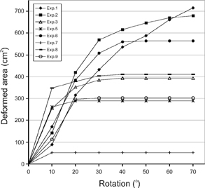
Diagram showing the increase in deformed area inside the box (i.e. north of the gate) for every 10° increment of rotation of the door for different experiments.
For experiments in which rift systems were well developed, these rift structures displayed rift shoulder uplift, resulting from the isostatic support of the lithosphere provided by the underlying glucose syrup.
In this section the results of experiments 1 to 9 will be described individually (see Figure 4 and movies).
Experiment 7 (Figure 4a, movie 1): In this experiment, the brittle top layer (0.6 cm) was directly superposed on top of the glucose syrup. This resulted in a very localised deformation pattern close to the gate, which got established within the first ~ 5° of rotation. Faulting was restricted to a rift system striking parallel to the door with normal faults striking slightly oblique to the rift axis. However, slight amounts of stretching of the brittle layer north of the rift zone was evident from the curvature of the east-west oriented grid lines. In between the rift system and the retreating door a narrow ridge developed.
Experiment 5 (Figure 4b, movie 2): In this experiment, the brittle top layer (0.6 cm) was directly superposed on top of the glucose syrup and the rate of opening was three times faster than in experiment 7. This resulted in a very localised and irregular deformation pattern, which rapidly migrated towards the north within the first ~ 10° of rotation but then stopped migrating and formed a through-going irregular rift structure parallel and closely behind the retreating door. This structure absorbed all of the continued extension. Most deformation in this experiment was accommodated by normal faults. A small number of strike-slip faults developed near the western corner of the gate.
Animation 2. Experiment 5
In this experiment, the brittle top layer (0.6 cm) was directly superposed on top of the glucose syrup and the rate of opening was three times faster than in experiment 7.
Experiment 8 (Figure 4c, movie 3): In this experiment, the brittle layer (0.5 cm) was superposed on the silicone layer (1.2 cm), overlying the glucose syrup, and the opening rate of the door was relatively slow (4°/h). This resulted in a relatively localised strain pattern, although less irregular compared to experiment 5. The deformation front migrated towards the north within the first ~ 15° of rotation and then stopped migrating. From this time onwards, the extension was limited to the deformed zone. In between the extending zone and the retreating door a relatively undeformed thin strip of material developed. In this experiment most deformation was absorbed by normal faults, while a few strike-slip faults developed along the western side of the deformed zone striking north to northeast. The normal faults obtained a strike oriented E-W in the west but progressively more NNW-SSE towards the east.
Animation 3. Experiment 8
the brittle layer was superposed on the silicone layer overlying the glucose syrup, and the opening rate of the door was relatively slow.
Experiment 9 (Figure 4d, movie 4): In this experiment, the brittle layer (0.8 cm) was superposed on the silicone layer (1.0 cm), overlying the glucose syrup. Again, this resulted in a relatively localised strain pattern. The deformation front rapidly migrated towards the north within the first 20° of rotation and then stopped migrating. From this time onwards, the extension was localised along a through going extending zone located just north of the retreating boundary, with in between a relatively undeformed strip of material. In this experiment most deformation was absorbed by normal faults, while a small number of strike-slip faults developed near the western corner of the gate striking northeast to north-northeast. The normal faults obtained a strike oriented E-W in the west but progressively more WNW-ESE towards the east.
Experiment 4 (Figure 4e, movie 5): In this experiment, a viscoplastic layer (0.2 cm) was inserted in between the brittle layer (0.6 cm) and the viscous layer (1.0 cm). This resulted in a localised deformation with well-defined elongated rift structures bounding relatively undeformed microplate-like segments. The deformation front migrated towards the north up to ~ 20° of rotation. Soon after, extension was mainly focussed along a through going extending zone located just north of the retreating boundary. As in most other experiments, a relatively undeformed strip of material developed in between the extending zone and the retreating door. Most deformation was absorbed by normal faults, while a small number of dextral strike-slip faults developed near the western corner of the gate striking northeast to north-northeast. The normal faults obtained a strike oriented E-W in the west, which became oriented progressively more NNW-SSE towards the east.
Animation 5. Experiment 4
A viscoplastic layer was inserted in between the brittle layer and the viscous layer (1.0 cm).
Experiment 3 (Figure 4f, movie 6): Here, a brittle (0.6 cm) layer was superposed on top of a viscous layer (1.2 cm), overlying glucose syrup. This resulted in a deformation pattern similar to that of experiment 4, although it is more diffuse with less well defined graben structures close to the retreating boundary. The deformation front migrated towards the north up to ~ 25° of rotation. Extension continued in the entire deformed region, but the amount of extension absorbed by the region close to the retreating boundary increased.
Animation 6. Experiment 3
A brittle (0.6 cm) layer was superposed on top of a viscous layer (1.2 cm), overlying glucose syrup.
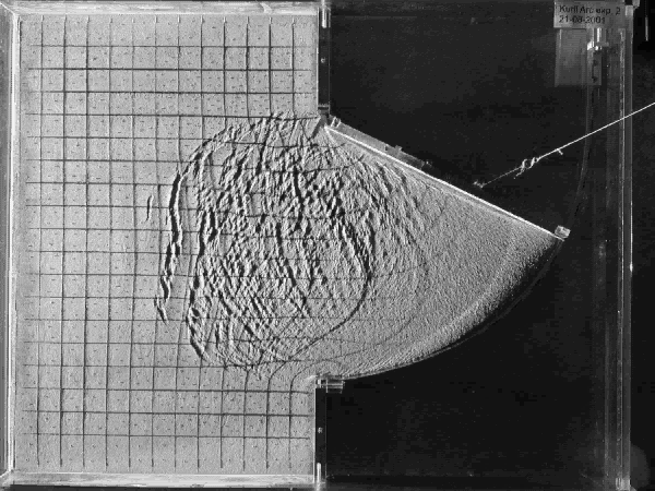
Experiment 6 (Figure 4g, movie 7): In this experiment, a brittle (0.5 cm) layer was superposed on top of a viscous layer (1.2 cm), overlying glucose syrup. This resulted in a more diffuse deformation pattern compared to experiment 3. The deformation front migrated towards the north up to ~ 35° of rotation. Extension continued in the entire deformed region, but the amount of extension absorbed by the region close to the retreating boundary increased. As in most experiments, a relatively undeformed strip of material developed in between the extending zone and the retreating door. Close to the retreating boundary normal faulting was the dominant type of deformation, while near the corners and further to the north deformation was mainly absorbed by conjugate (transtensional) strike-slip faults.
Experiment 2 (Figure 4h, movie 8): In this experiment, a brittle (0.4 cm) layer was superposed on top of a viscous layer (1.2 cm), overlying glucose syrup. This resulted in a diffuse deformation pattern. The deformation front migrated towards the north up to ~ 55° of rotation. Extension continued in the entire deformed region, but the amount of extension absorbed by the region close to the retreating boundary increased. Again, a relatively undeformed strip of material developed in between the extending zone and the retreating door. Close to the retreating boundary normal faulting is the dominant type of deformation, while near the corners and further to the north deformation is mainly absorbed by conjugate (transtensional) strike-slip faults.
Experiment 1 (Figure 4i, movie 9): In experiment 1, a brittle (0.4 cm) layer was superposed on top of a viscous layer (1.2 cm), overlying glucose syrup. The resulting deformation pattern is similar to that of experiment 2, although it is more diffuse with a higher fault density, owing to the higher strain rate in this experiment compared to experiment 2. The deformation front continued migrating towards the north until the end of the experiment. Extension continued in the entire deformed region, but the amount of extension absorbed by the region close to the retreating boundary increased.