The Experimental Procedure
Model
set-up , purpose and procedure
The models were intended to address two questions: 1) What
is the scale effect of ramp-flat thrust accommodation, and 2) How does
ramp-flat accommodation progress in flowing environments. The models were
prompted by the need to explore other alternative solutions of fault-fold
interaction than the concept of Rich (1934) of stair-case thrust propagation
which has dominated the geological literature. Because, the focus here
is on the mechanics of ramp/flat accommodation subsequent to faulting
in flowing environments, ramps with a 30§ inclination angle (with respect
to the maximum stress) were first induced in competent single layers and
it is modelled here how these layers accommodate slip in ductile surroundings.
A 30§ inclination for the ramp was chosen because ramps usually develop
at this angle in frictional plastic materials). The models were end-loaded
in a centrifuge spinning at 800 g (Fig. 2). This level of acceleration
was chosen to scale strength for gravity (see discussions later) and hence
prevent gaps from developing while slip accumulated along the ramp surfaces.
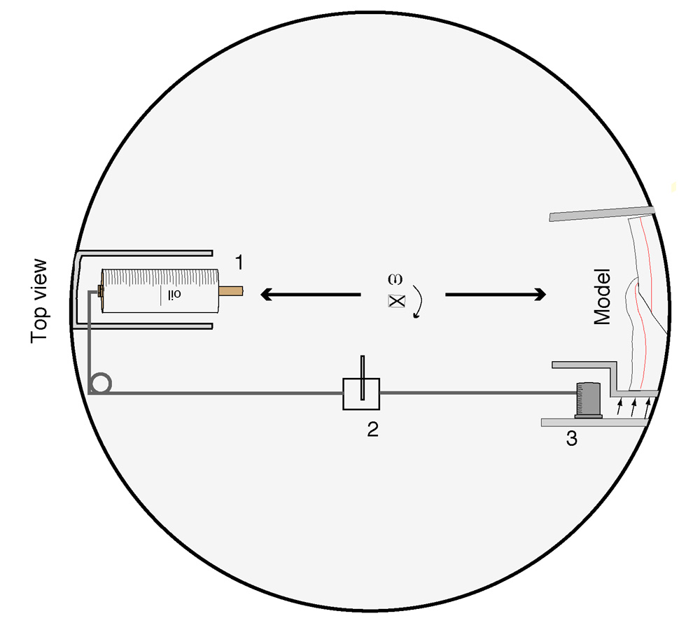 |
| Figure 2. Diagrammatic representation (not to scale) of top view of a hydraulic squeeze-box used to deform models in a centrifuge. 1. Hydraulic cylinder. 2. Magnetic valve used to switch on and off the compression. 3.Telescopic cylinders pushing the rear wall of a squeeze-box. (Select image for enlargement) |
The models represent layered materials arranged in different stratigraphic successions, with nearly initial constant thickness/width ratio (≈0.2) of the hangingwall blocks (Figs. 4 to 8). In a first arrangement the scale effect of ramp-flat accommodation was investigated by deforming models under normal gravity, and alternatively in a centrifuge (Fig. 4a). In a second set-up (Fig.5a), a competent layer with an induced ramp and overlain by ductile strata of various competence was detached above a rigid base. In a third arrangement (Fig.6a) the competent block was detached above ductile layers of various competence. This set-up was intended to study the geometry of ramp-flat accommodation emanating from ductile decollements. In a fourth set-up the plastilina hangingwall-footwall pairs were embedded in ductile strata of various competence (Fig. 7a). All models were deformed in plane strain in the transport direction. In the tests a rigid base lubricated with liquid soap provided a through-going decollement.
Materials
Plastilina
simulated the behaviour of competent sedimentary rocks such as sandstones
and limestones. Stress-strain curves for plastilina show strain-hardening
plastic behaviour (Fig. 3 a), at the confining pressures used in the centrifuge
(0-2 M Pa). The yield strength of plastilina increased with confining
pressure in the range ≈ 104-105 Pa. Creep viscosities after yielding
varied in the range 107-108 Pa s, depending on strain rate. This material
has the appropriate stress and strain-dependent rheological properties
to simulate the deformation of sedimentary rocks at deeper levels in the
crust (e.g. Hoshino et al, 1972).
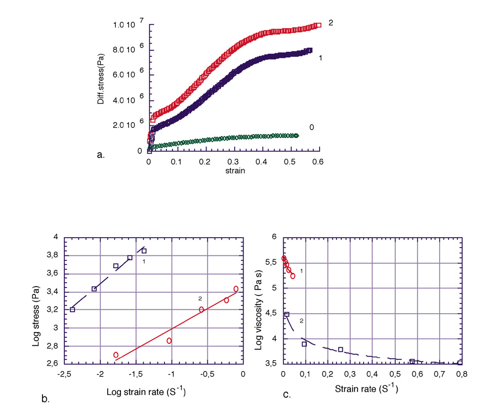 |
| Figure 3. a) Stress-strain behaviour of plastilina at different confining pressures ( 0, 1 and 2 in M Pa, respectively). b) Stress-strain rate behaviour of hardened (1), and softened (2) DC 3179 dilatant compound, used to simulate the incompetent surroundings in nature. c) Viscosity versus strain rate curves showing the strain rate softening behaviour of the incompetent surroundings. (Select image for enlargement) |
Two bouncing putties were used to represent the matrix materials. In one, DC-3179 bouncing putty (Hailemariam & Mulugeta, 1998) was mixed with sand to represent a relatively stiff matrix (hardened putty. 1 in Figs. 3 b and c). In the other, the same material was softened by admixing with aolic acid (softened putty, 2 in Figs. 3 b and c). These simulate ductile strata of various competence in nature, such as evaporites and shales. At room temperature and strain rate in the range 8x10⁻³ to 1.6x10⁻² s-1, the viscosity of the DC 3179 sand mixture varied in the range h ≈ (1.7-3.3)x105 Pa s with a power-law exponent (n≈ 1.2). For the same strain rate range the viscosity of the softened DC mixture varied in the range h ≈ 3 x103.5±0.5 Pa s with a power-law exponent (n ≈ 2). Thus, both matrix materials show strain-rate softening behaviour (Fig. 3c).
Scaling
Dynamic modelling
of ramp-flat accommodation in a centrifuge required scaling of strength
for gravity. This was necessary because strength is a fundamental property
at shallow levels in the lithosphere. A major problem in scale-modelling
under normal gravity is the requirement for model materials to be of extremely
low-strength such as cohesionless sand, to mimic the deformation which
takes place at a big-scale in nature. However, this restriction on model
materials imposed by scaling can be overcome by deforming models in a
centrifuge (e.g. Hubbert, 1937; Ramberg, 1981). Here, a hydraulic squeeze-box
operating in a centrifuge (Mulugeta, 1988) was used to study various ramp-flat
accommodation styles in rheologically stratified model systems (Figs.
4 to 7).
For a general 2-dimensional system, and neglecting inertia, the local stress equilibrium equation may be written as equation 1a.
| dsij/dxj+ rgi= 0 |
(1a)
|
The various quantities in eq. 1a may be written in a non-dimensional form (where primes denote non-dimensionalisation) as scale model ratios (eq. 1b).
| sr/xrrrgr(ds'ij/dxj) + r'(gi)=0 |
(1b)
|
where xr = (xj)m /(xj)n, rr = rm /rn; gr = gm/ gn ; sr = (sij)m/(sij)n are scale ratios of length, density, acceleration and stress, respectively. The subscripts m and n denote nature and model, respectively and i,j are cartesian components.
The first term on the left-hand side of eq. 1b expresses the balance between strength and gravity induced stresses. Dynamic similitude is satisfied in case this ratio remains invariant in model and prototype. Moreover, the value which this dimensionless stress ratio acquires determines the style of ramp-flat accommodation. For example, when this ratio is much bigger than one; or sr/xrrrgr>>1, gravity plays no or little role in hangingwall accommodation. In the reverse case, when sr/xrrrgr<<1 gravity dominates the style of hangingwall accommodation. In case sr/xrrrgr≈1, there is a near balance between yield stress and gravity stress.
If the value of the dimensionless strength to gravity induced stress ratio is the same in nature as in experiments;. xr= sr/rrgr. If in a model an acceleration of N times gravity is applied then the acceleration ratio gr = N, the scale factor for linear dimensions is then (eq.1b):
| xr= sr/rrN |
(1c)
|
In the centrifuge tests (e.g. Fig. 4c) scaling based on eq. 1c amounted to 1cm:0.5km, i.e using N= 800 and a yield strength of 10 M Pa for the prototype rocks e.g. sandstone, limestone in nature (e.g. Hoshino et al., 1972) and an average prototype density for sediments (e.g. sandstones, limestones) of 2.4 gm/cm3. For the model material (plastilina, Fig.3 a), a yield strength of 105 Pa and a density of 1.7 gm/cm3 was used. However, it must be realised that the scaling discussed above is approximate as the yield strength of both rocks and the model materials vary depending on strain and confining pressure. In the section below a number of dynamic models simulating ramp-flat accomodation styles are illustrated and discussed.