The
Experiment (continued)
The model was centrifuged for 9’30‘‘ at 700 g before a profile was cut for photographing. Two mushroom-shaped diapirs of the buoyant layer intruded the overburden and spread below the less-dense PDMS layer (Fig. 5). One diapir developed at the perturbation site and another one developed at the margin of the model. Moreover, two smaller diapirs reached the surface of the model (Figs. 5a-b). A fifth diapir, which formed close to the opposite margin ceased rising after only 1 cm, probably as a result of shortage in supply of the buoyant material (Figs. 5c-d). During their rise, the diapirs deformed the overburden units. A strain grid on top of the model deformed significantly due to emplacement of the diapirs underneath the PDMS layer (Fig. 5a). Peripheral skirts developed at the rims of the two spreading diapirs, whereas intense folding developed in the overburden between these two diapirs. Moreover, although being less dense than the other two materials, the PDMS overburden was dragged downward between the two diapirs (Figs. 5c–d).
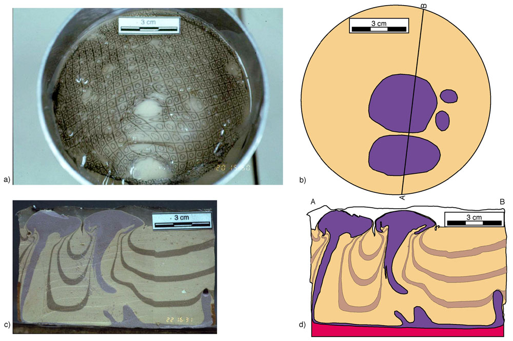 |
| Figure 5. a) Map view photograph of the experiment after the first stage of the experiment (centrifuging time: 9‘30‘‘). Two large diapirs and two smaller ones have spread under the PDMS layer and a thin cover of RG+P. A strain grid on top of the model deformed significantly due to emplacement of the diapirs underneath the PDMS layer. b) Sketch of the situation shown in Fig. 5a. The heads of the diapirs appear in blue, the overburden in beige. The cross section shown in Figs. 5c and d follows the line A-B. c) Photograph of a cross section through the model along line A-B in Fig. 5b. after emplacement of the first -generation diapir (centrifuging time: 9‘30‘‘). The RG1 forms two mushroom-shaped diapirs beneath a thin coating of RG+P. A third diapir at the right edge of the modell was aborted due to shortage in buoyant material. The passively stratified RG+P overburden was strongly deformed during the rise of RG1 and forms rim synclines around and in between the two diapirs. Even the less dense PDMS layer is affected by the emplacement of the two diapirs and was dragged downward as the diapirs spread at their level of neuutral buoyancy. d) Drawing of the situation shown in Fig. 5c. In addition the red RG2 layer attached to the model is shown.(Select image for enlargement) |
After photographing, the model was put together and welded by contact. A second buoyant layer of similar density and viscosity as the first buoyant layer, (differently stained RG2 layer) was attached to the bottom of the model. The model was then centrifuged for an additional 6’10‘‘ at 700g.
During
the centrifuging a second-stage intrusion of the second buoyant material
occurred. The intrusion of this buoyant material led to extensive spreading
and expansion of the first stage diapirs, whose surface area increased
by 25 to 50%. The two small diapirs unified to just one expanded diapir
(Figs. 6a-b). As a result of this ballooning the diapirs were overthrusted
upon each other and upon the overburden (Figs. 6c-d). Internal flow
within the diapirs led to peripheral skirts at the rims of the second
stage intrusions. The RG2 material rose along the stem of the pre-existing
diapirs, using them as mechanically weak pathways for its rise (Figs.
6c-d).
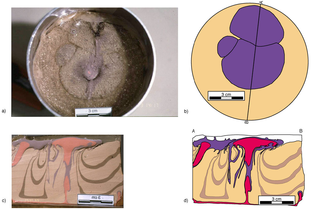 |
| Figure 6.
a) Map view photograph of the experiment after the second stage
of the experiment (centrifuging time: 6‘10‘‘). The
diapir bulbs have spread tremendously due to the emplacement of
the buoyant RG2 material: the surface area of the diapir closest
to point A along the profile line in Figs. 5b and 6b increased by
25% and the one in the centre of the model increased in size even
by 50%. The two smaller intrusions obviously unified and form now
one diapir whose surface area is 50% larger than the surface area
covered by its two precursors. b) Sketch of the situation shown
in Fig. 6 a). The heads of the diapirs appear in blue, the overburden
in beige. The cross section shown in Figs. 6c and d follows the
line A-B. c) Photograph of a cross section through the model along
line A-B in Fig. 6 b). after emplacement of the RG2 intrusions (centrifuging
time: 6‘10‘‘). The RG2 rose along the stem of the
pre-existing diapirs using them as mechanically weak pathways. When
reaching their level of neutral buoyancy, i.e. the bulb of the RG1
diapirs, the RG2 intrusions spread laterally leading also to an
expansion of their precursors. The final shape of the entire intrusive
complex is tabular. d) Drawing of the situation shown in Fig. 6
c). (Select image for enlargement) |
The results of the experiment can be summarized as follows. During the first stage of centrifuging two mushroom-shaped diapirs of the buoyant RG1 layer intruded the overburden to spread below the less-dense PDMS layer. During their rise, the diapirs deformed the overburden units and caused the formation of rim synclines around the diapirs (Figs. 5b and d). During a second stage of centrifuging a second intrusion occurred within the stem of the pre-existing diapirs. Once reaching the level of neutral buoyancy, the intrusive material spread laterally resulting in expansion of the overhang of the pre-existing diapirs. This lead to the formation of tabular intrusive bodies (Figs. 6b and d).