The experiment
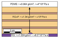
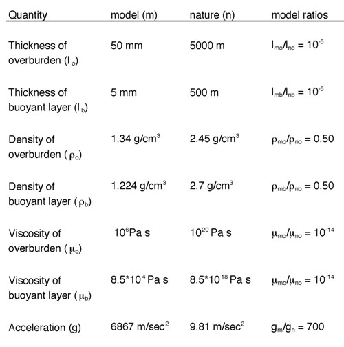
The experiment was aimed to study the subsequent and independent rise of two buoyant layers and the resulting structures. For this pupose a two-stage model was developed. In the first stage a buoyant layer (stained blue) was overlain by an overburden, which consisted of passively coloured denser layers (Fig. 4). Overburden was passively stratified in order to visualise internal deformation. After the first centrifuging stage a second buoyant layer (stained red, but with the same physical properties as the first buoyant layer) was attached to the bottom boundary of the overburden and the model was centrifuged for a second time. After each centrifuging stage the model was cut and photographed. The individual layers of the model described with their physical characteristics are as follows (from bottom to top): a 5mm thick buoyant lower layer of Newtonian Rhodorsil Gomme (RG1, r = 1.224 g/cm3 and µeff = 8.5*104 Pa s) simulating a partially molten magma (r = 2.45 g/cm3 and µeff = 8.5*1018 Pa s), a 50mm thick non-Newtonian overburden mixture of Rhodorsil Gomme + Plastilina (RG+P, r = 1.34 g/cm3 and µeff = 106 Pa s) simulating a silicic overburden(r = 2.7 g/cm3 and µeff = 1020 Pa s) in nature and a 10mm thick layer of PDMS (r = 0.964 g/cm3 and µeff = 4*104 Pa s) simulating a less dense overburden to prevent the diapirs from extruding. Scaling parameters are presented in Table 1. In order to govern the location of the diapir, a perturbation was initiated on top of the buoyant layer in the center of the model (Fig. 4).
 |
| Figure 4. Initial set-up of the experiment (PDMS = polydimethyl-siloxane, RG = Rhodorsil Gomme bouncing putty, P = plastilina). (Select image for enlargement) |
 |
| Table 1. Properties of the RG (Rhodorsil Gomme; buoyant) and RG+P (Rhodorsil Gomme + Plastilina; overburden) materials used in the presented model. |