Introduction
Tectonic plates often converge obliquely and major regional structures have been interpreted as the result of oblique shortening (transpression). Examples are the Alpine Fault zone in New Zealand (Norris et al. 1990), the San Andreas Fault zone in central California (Mount & Suppe 1987), the Mongolian Western Altai (Cunningham et al. 1996) and the Venezuela Andes (Colletta et al. 1997). Transpression in the upper crust is dominantly accommodated by brittle faulting and is generally thought to be at least partly controlled by distributed flow of the underlying ductile parts of the crust and mantle (England 1989).
We performed a series of analogue modelling experiments to investigate the development and evolution of structures in zones of continental transpression. Models were analysed by X-ray computerized tomography (CT; Hounsfield 1973), a technique which makes it possible to visualise the interior of a model without destroying it. Some of the experimental results have been previously published, illustrated with surface views, and CT images through selected stages of the model evolution (Schreurs & Colletta 1998). In this paper emphasis is placed on computer animations of these experiments, which show in considerably more detail the development and evolution of transpressional structures.
Models were deformed in the experimental apparatus shown in Fig. 1. Transpression consisted of two components: a shear component at the base of the model (in a direction parallel to the longitudinal vertical walls) and a transverse shortening component (perpendicular to the longitudinal vertical walls). The base of the deformation box consisted of two plates (Fig. 1B). One of them was moved past the other by a geared motor drive. Some 60 plexiglass bars, each 5 mm wide, 1 cm high, and 70 cm long, were stacked like cards between two parallel wooden bars, which are attached to the base plates. The plexiglass bars were transversally confined on either side by a pivoting wooden bar. A 5 mm thin layer of viscous polydimethylsiloxane (PDMS; Weijermars 1986) was placed on the array of plexiglass bars, and sand and glass powder (with an average grain size of 100 µm) were alternately poured on top to produce a stratified model (total thickness 3.5 cm). A square grid of colored sand markers was traced on the upper surface. Initial length of the model was 70 cm and initial width was 26 cm. Transverse borders of the model consisted of rubber sheets. As one of the base plates was displaced, the plexiglass bars slipped past one another and the initial rectangular configuration became a parallelogram and caused the shear component of deformation in the overlying model. At the same time transverse shortening was produced by displacement of one of the longitudinal vertical walls (C in Fig. 1b), which overlie both the array of plexiglass bars and their two confining pivoting wooden bars. The viscous PDMS at the base of the model served two purposes: it distributed the applied shear movement homogeneously and at the same time it simulated a horizontal detachment layer, because it was weaker than the overlying sand and glass powder. Movements of both longitudinal vertical wall and base plate occurred at pre-set velocities by stepper motors with computer control.
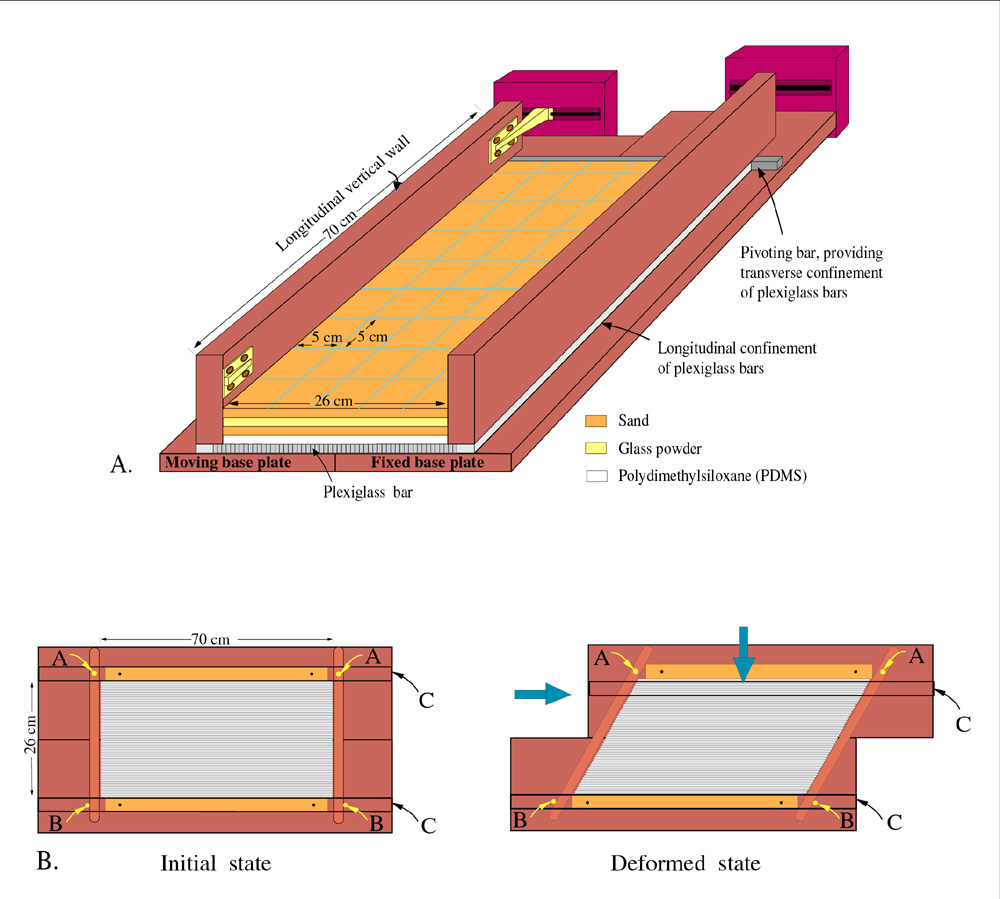 |
| Figure 1. (A) Perspective view of experimentsal apparatus. Transverse borders of the multilayer model consisting of rubber sheets are not shown. (B) Plan view of base of experimental apparatus. Longitudinal vertical sidewalls, whose outline is marked by C, overlie the plexiglass bars. Transverse movement of one of these walls induced the shortening component of transpression. A and B indicate location of small pins that guide the pivoting wooden bars. (Select image for enlargement) |
Most previous studies on oblique shortening involved a single basal discontinuity for the shear component of deformation, causing localisation of structures in the immediate vicinity of the discontinuity. This is in contrast with the experiments shown here, in which the shear component of deformation is distributed, resulting in the development of several fault zones and thus allowing to study their interactions. The boundary conditions for four transpressional experiments (Table 1) were identical, except for the velocity of the base plate which induced the dextral shear component of transpression, hence the ratio between shear strain rate and shortening strain rate. Varying this parameter between experiments allowed us to investigate its influence on fault development in the brittle layers.
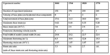 |
| Table 1. Experimental parameters. Shear strain and shear strain rate were calculated using the width of the array of plexiglass bars (28.5 cm), which was slightly larger than the initial width of the overlying model (26 cm). Model widths were used to calculate shortening and shortening strain rate. |