Diffusive Gain or Loss not Isotropic
The present decade is interesting in that two different ideas about diffusive gain and loss are in use. Consider an extensive sample of material in which the stress is everywhere anisotropic and is also non-uniform. In particular consider a small spherical element somewhere within the sample: if the material is viscous but non-diffusing the element will undergo strain at constant volume, but if it is self-diffusing as well as viscous, it will deform with principal strain rates that in general do not conserve volume. In principle, one could run parallel experiments and, by subtraction, isolate just the strain rates attributable to the diffusive process. Then the two ideas are:
(1) these isolated or partial strain rates must be the same in all directions (i. e. diffusion by itself can turn a sphere only into a smaller or larger sphere)
or
(2) the partial strain rates form a set whose principal values at any point are in general different from one another (i. e. diffusion by itself could turn a sphere into an ellipsoid).
In the first theory, to predict diffusive effects one looks at magnitudes and gradients of just the mean stress; in the second theory, one has to look at all three separate principal-stress magnitudes rather than just their mean.
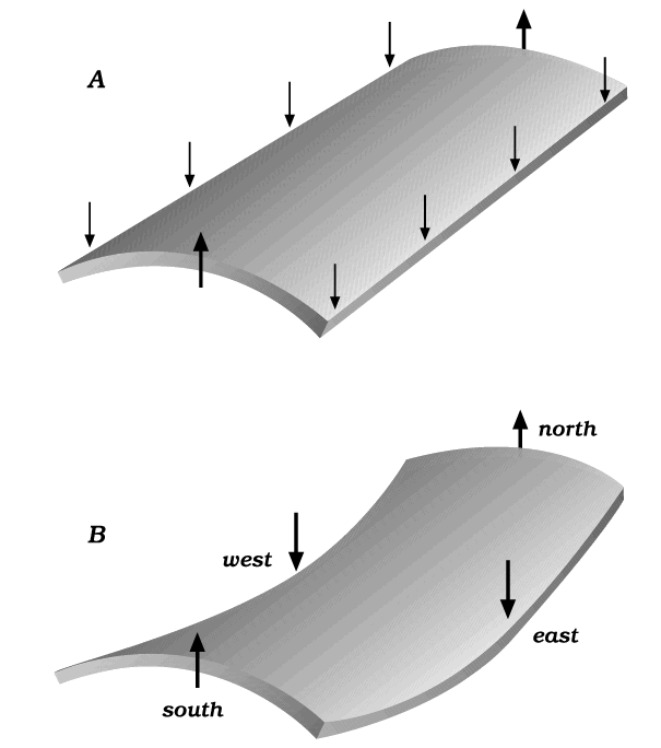
For illustration, consider the bending experiments in Figure 6. Everyone agrees that in cylindrical bending, diagram A, diffusion can be initiated with a flux from the inner surface to the outer. But in saddle bending, diagram B, opinion is divided. In the center of the slab, the mean stress is uniform from top to bottom, but vertical planes running north-south are compressed more strongly normal to the plane in the lower part of the test slab than in the upper part, while vertical planes running east-west are compressed more strongly in the upper part; that is, there are gradients in the normal-stress components on these planes, that cancel each other out to give no gradient in mean stress. One wonders, Do the gradients drive diffusive fluxes that contribute to the deformation of the saddle? As far as I know, no such experiment has been reported. To imagine spherical atoms like billiard balls favors the idea of no diffusion in such a slab, but to imagine dislocation loops, incomplete atom-planes and dislocation climb favors the idea that the gradients could drive some loops to shrink and some to swell. I wish to give both ideas serious attention and respect, but in this section it is the second that we explore.
Figure 6. Two possible bending experiments

Two possible bending experiments where diffusive transport in a vertical direction might occur.
[Idea 3: if the material itself is anisotropic, --- for example, having a microstructure that is flaky or fibrous --- loss by diffusion may be greater in one direction than in another for that reason. But this idea is wholly separate: in the present paper, the material itself has no anisotropy, it is from the stress state that the anisotropy of the strain rates arises.
For a fourth idea, concerning gain or loss at an interface, see Fletcher (this volume).]
The Broad Field
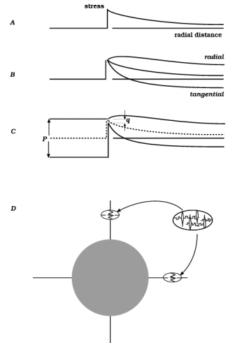
Using reference directions as in Figure 2, consider a line from the inclusion's center running north. As already shown, the profile of mean stress along such a line is as in Figure 7A. In absence of diffusion, if the inclusion is rigid, profiles of the north-south or radial stress and the east-west or tangential stress are as in Figure 7B (or if the inclusion is stiff but not rigid, see Figure 7C; here the separation distances p and q are in proportion with the materials' viscosities). In all three diagrams, for the mean stress the diminution outward (to northward) is proportional to 1/r2 and, in the manner of Figure 2B, the upward curvature along this profile is exactly matched by a downward curvature of lines in and out of the page, --- the two curvatures balance. We now note that for the tangential stress, the upward curvature is clearly greater than for the mean stress and except right at the interface, the downward curvature is less; by contrast, for the radial stress, the upward curvature has been largely lost. Therefore, speaking geometrically, the tangential-stress surface has a net upward curvature and the radial-stress surface has a net downward curvature. If gradients on these surfaces separately drive diffusion, the tangential-stress variation will drive a net tangential accumulation outside the north part of the interface, and the radial-stress variation will drive a net radial loss; see Figure 7D. Along a line out to eastward, all the opposite effects occur, so that radial-stress variation drives a flux from north to east, whereas tangential-stress variation drives a flux from east to north. So far it remains true that no material element either swells or shrinks in volume, but in the north, there is radial shortening and tangential elongation while in the east, there is radial elongation and tangential shortening. It is reassuring to note that these are strains of the same type as are occurring simultaneously by viscous creep; anisotropic strain by diffusion adds to the deformation, it makes the material yield more readily; one sees greater strain rates and smaller stress peaks when this kind of diffusion is occurring than if diffusion were to act isotropically or not at all.
Figure 7. Stress profiles along the north axis

Stress profiles along the north axis and consequent gains and losses of material.
(One might ask, about the north region for example: if, as above, radial-stress variation drives radial loss of material and tangential-stress variation drives tangential gain, would not most of the material that moves simply "slip round the corner" without ever leaving the site? No, radial loss and tangential gain at the same location go on at whatever rate the viscosity permits, given the stress difference at that location. We are looking here at additional radial loss that occurs because the radial compression is lower on either side of the north point, at neighboring points just to the east and west.)
Details close to the inclusion
Two concepts were illustrated in Figure 5 for the region close to the cylindrical interface. Figure 5A suggests a discontinuity: the idea is that a film of newly-deposited material forms and separates the two regions whose stress fields etc. are described by the equations. In Figure 5B, by contrast, a change in the curvature of the stress surface is suggested. Such a stress field would lead to accumulation not at the interface but in the region close to the interface; material arriving from upstream would accumulate in a dispersed manner continuously throughout the material of the matrix in that region. The occurrence of augen suggests that Figure 5A is closer to what happens in deforming rocks, whereas Figure 5B is closer to what happens in many other instances of chemical diffusion. Actually, even in rocks, the loss of material by diffusion may occur in a dispersed, quasi-continuous manner; it may be only the gain or deposition process that is localized in well defined pockets. Anyway, setting reality aside, the theoretical work I wish to extend (Fletcher 1982; Stephenson 1988; Finley 1994) is more in the manner of Figure 5B and therefore a description more like 5B than 5A was sought.
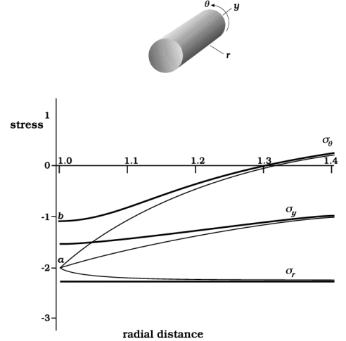
The relevant equations are given in Appendix 3, and some of the results are shown in Figures 8 and 9. Figure 8 shows stress magnitudes along a radial line to the east in the direction-system of Figure 1. The effects of diffusion are greatest close to the interface. Again the effect is to diminish and smooth out peaks and extreme values; in particular the tangential compression sq no longer drops to such an extreme value. The change of curvature proposed in Figure 5 is seen: concave-upward curvature is noticeable in sq and perceptible in sy . By themselves, these upward curvatures would lead to accumulation of diffusing material and elongation in the tangential and y-directions. However, the theory assumes a totally coherent interface: the matrix is taken as firmly glued to the rigid inclusion and cannot elongate at the interface except radially outward. Instead of causing lateral swelling, then, the influx of diffusing material leads to a stress build-up e.g. from a to b in Figure 8; the material still swells, but constrictive stresses force the effect to occur by radial elongation.
Figure 8. Stress profiles along the east axis

Light lines are profiles unaffected by diffusion; in that condition, sy and the mean stress are equal so the curves here match Figure 7 (inverted) and Figures 5 and 2. Heavy lines show modified stress profiles such as might be present when diffusive transport occurs and gives unequal contributions to the strain rates radially and tangentially. In particular, the concave-upward part of the profile for sq leads to accumulation of material and a tendency toward tangential elongation, but this is exactly countered by σq now being greater than σy and σr which by itself would give tangential shortening. Compared with the light-line profiles, the change in magnitude of σq and the change in curvature have to have equal and opposite effects on the tangential strain rate, if the matrix is to remain coherent with the inclusion.
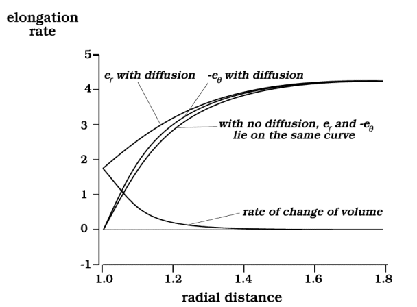
Figure 9. Strain-rate profiles along the east axis.

The matrix swells, gaining material by diffusion, but because of being coherent with the rigid inclusion, at the interface the swelling is entirely by radial elongation.
The strain-rate consequences are seen directly in Figure 9. The radial elongation εr is noticeably larger when diffusion operates, whereas the tangential shortening hardly changes. Of course the latter is artificially pinned at zero at the interface by our assuming perfect coherence. With this constraint, it appears that as far out as 1.5 or 1.6 on the radial scale, the tangential shortening is actually a little greater when diffusion operates, as if the stress field over-compensates; but the equations are only a coarse approximate solution, and this detail in the curves for eq may be insignificant. The more important point is that we now see unequal strain rates in the radial and tangential directions, and increases of volume due to diffusion that are distributed through the matrix in a continuous manner rather than as a discrete sliver of new material at the interface.
Numerical values
Figures 8 and 9 show differences between behavior when diffusion is occurring and when it is not. The differences are easily seen and are linked to important concepts, but in the particular example calculated, they do not amount to a large change in the overall strain field. This conclusion can be illustrated in geological terms as follows.
Let the rigid inclusion be a chert nodule in limestone, idealized to a circular cross-section of diameter 2 cm and a much greater length. Let the limestone be deformed, for example in the hinge of a fold, so that a region around the nodule is changed from a 10-cm square to a rectangle 6.25 cm by 16 cm. We focus attention on points 5 mm out from the nodule boundary, or 1.5 cm from its centerline. If the nodule were as readily deformable as its matrix, in the direction of maximum elongation such a point would move through 9 mm to end 2.4 cm out. If the nodule is rigid and no diffusion occurs, the motion would be reduced to 1 mm; a rigid nodule powerfully inhibits deformation of its immediate surroundings. Now let diffusion run, with stresses as in Figure 8 yielding strain rates as in Figure 9: the outward motion of the point in view would increase only about 14% --- an extra motion of only a fraction of a millimeter during the total episode of deformation. This small change is of course tied directly to the particular example described in Appendix 3, and specifically to the value of the characteristic length L in that example (0.188 x the inclusion radius). If L had a larger value, the effect of diffusion would be greater; even so, part of the effect is to reduce the stress concentrations; the effect of diffusion does not appear wholly in the form of enhanced strain rates.
Need we look at actual stress magnitudes and duration of the deformation episode? No, the length L is the essential parameter. Suppose (unrealistically) that the change in dimensions of the reference square from 10 cm to 16 cm occurred at a constant strain rate of 3.10-14 per sec for (6.7).1012 sec, in a rock of effective viscosity 1020 Pa-sec; then the driving stress difference must have been 12 MPa, and the diffusion coefficient K = 9x10-27 m2-Pa-1-sec-1, (from L2/4N). Now suppose the temperature or the pore-fluid chemistry were different so that the effective viscosity was only half as much: the time for the deformation would change, but experience indicates that K would increase by a factor close to 2 --- (K and N varying inversely), --- so that L would not change and, like the total strain, the same total diffusive effect would be gained at twice the rate in half the time.