The classical solution extended
An intuitive picture of the stress state close to a stiff inclusion is shown by the shading in Figure 1. The quantity indicated is the mean stress, with two high-compression regions outside the inclusion to north and south and two regions of lower compression, "stress shadows," to east and west. The variation in mean stress is shown more quantitatively in Figure 2A; if, as shown in Figure 1, the remote stress field has principal stresses M+S and M-S, then against a rigid inclusion in absence of diffusion, the extreme values of the local mean stress are M+2S at the north and south interface points, and M-2S at the east and west points (Muskhelishvili 1963; Jaeger and Cook 1979). The values diminish outwards in proportion with the square of the radius, so that at r = 2R, the anomalies are only one-quarter of their maximum values, and so on (r = radial coordinate; R = radius of the inclusion, hereafter taken as the unit length).
Figure 1. Cross-section of a long stiff cylindrical inclusion in a less stiff matrix.
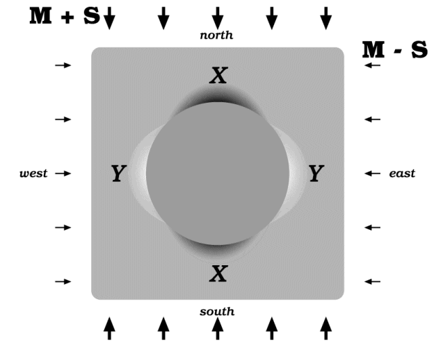
The matrix is assumed to extend without limit, and the uniform stresses shown are actually applied at a great distance from the inclusion. The shading shows locations of maximum and minimum compression.
Algebraic details are given in Appendix 1, but already an important point about the mean-stress surface can be noted. If diffusion were to start up but was sufficiently slight that the stress field was hardly modified, the gradients in Figure 2A could be thought of as the driving agents. Focussing, for example, on the east valley, we should expect diffusion into the valley from either side and also from its shallow upper end (the foreground of Figure 2A). But the valley-bottom descends more steeply close to the inclusion, and the variation specifically with radius to the power of two has the following property: if the diffusive flux is proportional to the mean-stress gradient, then over any section of the valley floor, the material diffusing out from the lower end exceeds what diffuses in at the top end by just enough to exactly balance the inflow at the sides; see Figure 2B (i) and (ii). The profile across the valley is concave upward but the profile along the valley is concave downward; if we write for the mean stress and use local axes x and y as in Figure 2B (iii), then
Figure 2. A surface representing the mean-stress magnitude
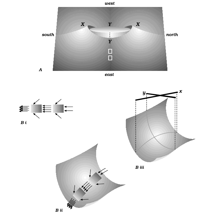
Shown here in the neighborhood of the inclusion; locations X,X and Y,Y are as in Figure 1. Far from the inclusion, the surface is flat at magnitude M. Part B of the figure shows details of the east valley.
The fact that this particular balance exists means that diffusion could indeed run without affecting the stress field. As so far described, the diffusion process would have no effect on the material’s shape at any point. If we could just take care of effects at the interface, by finding a home for material that runs to the interface down the east and west valleys and supplying material so that it can run away from the interface at the north and south humps, we should have a system capable of running in a steady state.
To pursue this possibility, imagine that the cylindrical inclusion is stiff but not totally rigid. The pattern of mean stress would be changed only slightly, but the velocity field would change in an important respect: the cylinder’s boundary would no longer be stationary but would become a changing ellipse in cross-section; if the cross-section were a circle at one moment, at later times it would become shorter north-south and longer east-west. An illustration of such a change is given in Figure 3.
Figure 3. Deformation of a grid that is initially composed of uniform squares.
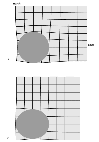
Part A shows how such a grid would change if the inclusion were rigid and the matrix was deformed. Part B shows how the grid would deform if the remote surroundings stayed still but the inclusion changed shape. We can assume that the inclusion is rigid, as in A; but in the surroundings, suppose that the change shown in B is superimposed on the change shown in A: then a gap would develop to east and west of the inclusion, and a conflict would exist to north and south, with inclusion and matrix both imagined to occupy the same space. Diffusive mass transfer could obviate the gap and the conflict.
The point now to be made is: if this velocity field were to exist in the inclusion’s surroundings when the inclusion was in fact totally rigid, there would be a mass conflict at the north and south interface points (excess material to be got rid of) and a mass deficit at the east and west points (material would be needed to fill the gap). These are exactly the conditions that diffusion could take care of. In other words, if diffusion were to occur, the matrix could move as if the inclusion were deformable when in fact it was not; or more generally, if the inclusion were slightly deformable, the matrix could move as if it were more readily deformable because of the easing effect of the diffusive fluxes.
The preceding ideas are quantified in Appendix 1, and illustrated in Figure 4. If stiff viscous materials were important in everyday engineering, the equations in Appendix 1 would have been worked out long ago; the reason that they or some equivalents have not been worked out before is partly that elastic behavior has commanded more attention, and partly that diffusion effects in everyday engineering occur on very short length scales. A conclusion from Appendix 1 is that for diffusion effects to be of consequence, the radius of a rigid inclusion needs to be only a few multiples of the material’s characteristic length. (For comment on the idea of characteristic length, see Appendix 2). This means that in metal alloys we would need to be looking at resistant particles measured in nanometers, and in dry, hot creeping mineral aggregates we would need inclusions measured in micrometers (Bayly 1992, p. 120). By contrast, the purpose here is to contribute to the study of outcrops: we seek relations between stresses and strain rates that allow for diffusive mass transfer so as to understand augen, stylolites, saddle reefs etc., with dimensions in centimeters or meters. Fletcher (1982) has addressed this point and suggested that for a rock that self-diffuses by movement of dissolved quartz, the characteristic length might be of the order of 10 cm; but of course there remains considerable doubt about what behaviors in a wet granular rock resemble behaviors in an idealized continuum.
Figure 4. The intensity of the diffusive fluxes.
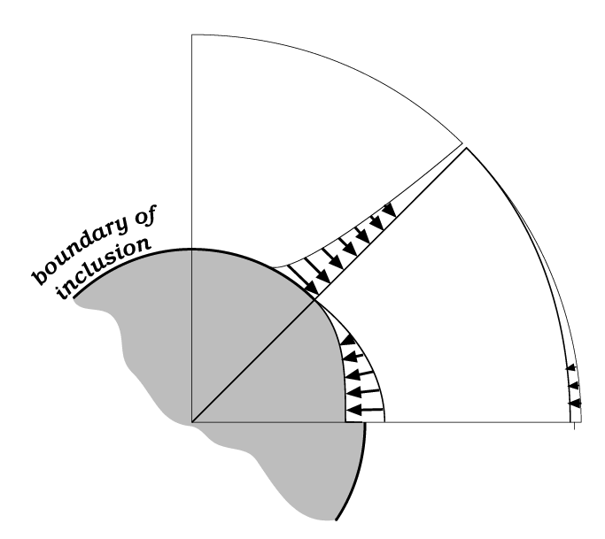
The tangential flux is greater close to the inclusion than farther out and is at a maximum across a plane at 45°, diminishing to zero on planes running due east or north. The radial flux similarly is strongest at the interface, but is zero at 45° and at a maximum along an east line (flux inward) or a north line (flux outward).
Defects in the description so far
The description so far is defective in that:
(1) it describes only effects driven by the mean-stress magnitudes and gradients, --- no attention has yet been paid to σr and σq separately.
(2) it does not show any volume-element of material shrinking or expanding, --- losing or gaining material, --- by the diffusive mass transfer. The material that diffuses is deposited all in one location, at the interface, separate from the material it has diffused through. I would like to make the change illustrated in Figure 5, from the condition in part A to the condition in part B; that is, from the condition where deposition is strictly at the interface to a condition where deposition is distributed throughout a finite region of the host material.
The remainder of the text is an effort to circumvent these two defects.
Figure 5. Possible profiles of mean stress along the east valley.
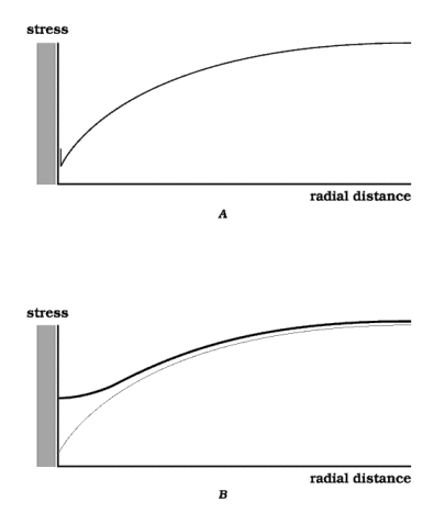
Part A shows a profile as discussed in the text and shown obliquely in Figure 2. It is in two parts, a portion that is concave downward along its full length and a vertical portion or step at the interface (represented by the short vertical line just outside the interface). These two parts meet in a point that can be regarded as a concave-upward portion with infinite curvature and infinitesimal width. By contrast in part B, the portion that is concave upward is of finite width. A stress field with this type of profile leads to material accumulating by diffusion in a dispersed manner throughout a finite region of the host material, rather than in the localized manner of part A. It is this type of profile that is sought in the second half of the text. For part B, one can still assume that the north profile has the form of the east profile inverted, and that exactly the same distribution of material is lost from north and south regions as is gained by the east and west regions; those aspects of the problem remain simple.
