| Schreurs,
G. and Colletta, B.
2002. Analogue
modelling of continental transpression. Schellart, W. P. and
Passchier, C. 2002. Analogue modelling of large-scale tectonic processes.
Journal of the Virtual Explorer, 7, 67-78. |
|
Analogue
modelling of continental transpression
|
|
Appendix
1 - Movies
|
|
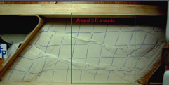
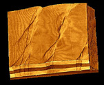
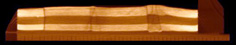
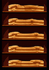
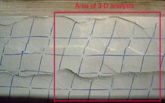
Movie
1661-01. Movie illustrating the progressive development of convergent
strike-slip fault zones in plan view (experiment 1661). The first
frame shows the location of computerized tomography (CT) acquisition
planes. Rectangle in last frame indicates area of 3D analysis by X-ray
CT (27 x 23.8 cm; see Movies 1661-03, 1661-04, 1661-05 and 1661-06).
Initial grid spacing is 5 cm. Time between frames is about 10 minutes.
(Select
image to view movie) |
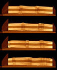 |
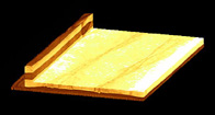
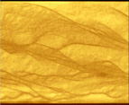
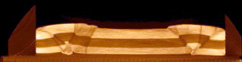
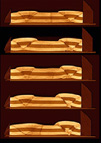
Movie
1661-02. Movie of cross-sectional evolution of experiment 1661. Location
of CT sections A-D is given in the first frame of Movie 1661-01. Note
that the position of the model changed with respect to the fixed CT
image acquisition planes during progressive deformation. Initial width
of model is 26 cm; initial height is 3.5 cm. Time between frames is
8 minutes. (Select
image to view movie) |
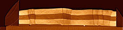 |
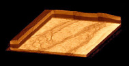
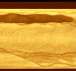
Movie
1661-03. Movie illustrating the geometry of convergent strike-slip
fault zones by a series of serial vertical sections. Each of the 135
frames represents a 2mm thick cross-sectional CT slice. (Select
image to view movie) |
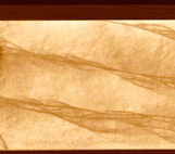 |
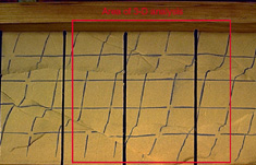
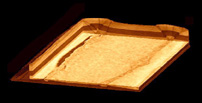
Movie
1661-04. Movie showing serial horizontal sections through convergent
strike-slip fault zones. Major fault zones strike at about 15°
to the longitudinal sidewalls. Horizontal sections were computed from
3D data set. First frame is near the base of the brittle layers. Vertical
distance between frames is 0.5 mm. Computer animation shows 66 frames
at three frames per second. (Select
image to view movie) |
 |
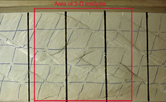
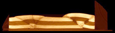
Movie
1661-05. Movie of rotating 3D perspective view of transpressional
fault zones. Area of 3D CT analysis is indicated in Fig. 2E and in
last frame of Movie 1661-01. (Select
image to view movie) |
 |
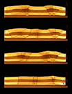
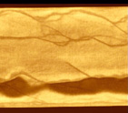
Movie
1661-06. Movie of cut-out 3D views of final deformation stage. Computer
animation shows 28 frames at 4 frames per second. (Select
image to view movie) |
 |
Movie
1764-01. Movie illustrating the progressive development of structures
in plan view (experiment 1764). The first frame shows the location
of CT acquisition planes. Rectangle in last frame indicates area of
3D analysis by X-ray CT (27 x 23.2 cm). Initial grid spacing is 5
cm. Time between frames is 10 minutes. (Select
image to view movie) |
 |
Movie
1764-02. Movie of cross-sectional evolution of experiment 1764. Location
of CT sections A-D is given in the first frame of Movie 1764-01. Note
the lateral changes in fault dip along strike. Initial width and height
of model is 26 and 3.5 cm, respectively. Time between frames is 8
minutes. (Select
image to view movie) |
 |
Movie
1764-03. Movie illustrating the fault geometry by a series of serial
vertical sections. Steep strike-slip faults branch at depth with oblique-slip
thrust faults. Each of the 135 frames represents a 2mm thick cross-sectional
CT slice. (Select
image to view movie) |
 |
Movie
1764-04. Movie showing serial horizontal sections through final deformation
stage. These sections show the complex fault pattern at depth in great
detail. Note the oblique thrust faults (and associated vertical relief)
between major convergent strike-slip fault zones in upper part of
movie. First frame is near the base of the brittle layers. Vertical
distance between frames is 0.5 mm. Computer animation consists of
64 frames. (Select
image to view movie) |
 |
Movie
1764-05. Movie of cut-out 3D views of final deformation stage. Computer
animation shows 28 frames at 4 frames per second. (Select
image to view movie) |
 |
Movie
1820-01. Movie illustrating the progressive development of structures
in plan view (experiment 1820). Main faults trend subparallel to longitudinal
sidewalls. The first frame shows the location of CT acquisition planes.
Rectangle in last frame indicates area of 3D CT analysis (27 x 22.7
cm). Initial grid spacing is 5 cm. Time between frames is 10 minutes.
(Select
image to view movie) |
 |
Movie
1820-02. Movie of cross-sectional evolution of experiment 1820. Pop-up
structures form initially. Steep strike-slip faults form at later
stages and occur either confined within pop-up structures or between
different pop-up structures. Location of CT sections A-E is given
in the first frame of Movie 1820-01. Initial width and height of model
is 26 and 3.5 cm, respectively. Time between frames is 10 minutes.
(Select
image to view movie) |
 |
Movie
1820-03. Movie illustrating the fault geometry by a series of serial
vertical sections. Fault dip changes along strike in the right-hand
side of the images. Note also how subvertical strike-slip faults change
their dip direction along strike and merge at depth with bounding
thrust faults. Each of the 135 frames represents a 2mm thick cross-sectional
CT slice. (Select
image to view movie) |
 |
Movie
1820-04. Movie of serial horizontal sections through final deformation
stage. Major faults are subparallel to the longitudinal borders of
the model. First frame is near the base of the brittle layers. Vertical
distance between frames is 0.5 mm. Computer animation consists of
60 frames. (Select
image to view movie) |
 |
Movie
1820-05. Movie of cut-out 3D views of final deformation stage. Computer
animation shows 28 frames at 4 frames per second. (Select
image to view movie) |
 |
Movie
1770-01. Movie illustrating the progressive development of structures
in plan view (experiment 1770). Main thrust faults trend parallel
to longitudinal sidewalls. The first frame shows the location of CT
acquisition planes. Rectangle in last frame indicates area of 3D CT
analysis (27 x 22.7 cm). Initial grid spacing is 5 cm. Time between
frames is 10 minutes. (Select
image to view movie) |
 |
Movie
1770-02. Movie of cross-sectional evolution of experiment 1770. Model
evolution dominated by thrust faulting. Location of CT sections A-E
is given in the first frame of Movie 1770-01. Initial width and height
of model is 26 and 3.5 cm, respectively. Time between frames is 10
minutes. (Select
image to view movie) |
 |
Movie
1770-03. Movie illustrating the geometry of the structures by serial
vertical sections. Subvertical strike-slip faults within pop-up structures
change their dip direction along strike and merge at depth with bounding
thrust faults. Each of the 135 frames represents a 2mm thick cross-sectional
CT slice. (Select
image to view movie) |
 |
Movie
1770-04. Movie of serial horizontal sections through final deformation
stage. Major faults are subparallel to the longitudinal borders of
the model. Some strike-slip faults strike oblique to the longitudinal
sidewalls. First frame is near the base of the brittle layers. Vertical
distance between frames is 0.5 mm. Computer animation consists of
60 frames. (Select
image to view movie) |
 |
Movie
1770-05. Movie of cut-out 3D views of final deformation stage. Steep
strike-slip faults within pop-up structures change their dip direction
along strike. Computer animation shows 28 frames at 4 frames per second.
(Select
image to view movie) |
|
|
|